
AFPM Core Sizing & Engineering Decision Guide
Estimate iron mass and frequency. Prepare an AFPM core review brief.
Executive Engineering Takeaways: AFPM Core Design
Start with these decisions; source-backed facts and editorial review guidance are identified separately.
Size the iron before discussing performance
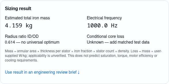
The tool calculates geometry and electrical frequency. Iron fraction, density and per-stator thickness remain explicit assumptions; torque, efficiency and thermal limits require a motor model.
Basis: editorial technical design guidance. Validate against project-specific electromagnetic and mechanical requirements.
Compare samples with the same test conditions
Ring size, flux density, frequency, material processing and waveform change the meaning of a W/kg figure. A small coupon alone cannot establish the loss of a complete tooth.
Evidence and scope: Somaloy® 5P material data, 2274HOG-2 (2024) · IEC 60404-6:2018 — AC ring-specimen measurements
Choose a flux path before choosing a material
A yokeless segmented core removes the stator yoke; a yoked or slotless architecture has different return paths and assembly interfaces. Material selection follows that geometry.
Evidence and scope: YASA axial flux motor technology
Qualify the insulation as a system
Type I and Type II use distinct qualification routes. Specify the actual converter waveform, temperature and installation conditions before agreeing acceptance limits.
Evidence and scope: IEC 60034-18-41:2014+AMD1:2019 — Type I insulation · IEC TC2 reference: IEC 60034-18-42 — Type II insulation
Treat cost and capability as quotation inputs
Prototype machining and production compaction are different process routes. Request separate costs, inspection scope and validation evidence rather than assuming a tooling saving or fixed lead time.
Evidence and scope: Sampling & prototypes
Comprehensive Technical Reference Chapters
In-depth engineering analysis covering 3D electromagnetics, material science, compaction kinematics, GD&T stack-up, and automotive quality assurance.
Trace the three-dimensional flux path
Map the return path and local flux peaks before picking a core route.
Follow the field through the component before selecting a material or lamination orientation.
An AFPM air gap carries flux along the shaft axis. Tooth shoes, slot openings and return paths can introduce additional spatial components. The orientation of a lamination stack therefore matters as much as the material family.
SMC supports flux in multiple directions, but particle insulation does not remove every loss mechanism. Laminated steel remains an option where segmentation and sheet orientation manage the field. Compare candidate geometries using the same electromagnetic boundary conditions, then test representative components.
| Route | Potential benefit | Required check |
|---|---|---|
| SMC tooth | Shape freedom in multiple flux directions | Grade, density and component loss |
| Laminated tooth | Useful in-plane magnetic path | Sheet orientation and transverse flux |
| Hybrid assembly | Different materials at different features | Interface gaps and assembly repeatability |
Editorial decision framework; no supplier capability or universal acceptance limit is implied.
Evidence and scope: Somaloy® 5P material data, 2274HOG-2 (2024)
- Identify the local field direction at each interface.
- Compare complete components rather than material labels.
Evidence and scope: Somaloy® 5P material data, 2274HOG-2 (2024)
Yokeless, yoked, dual-stator and slotless layouts
Topology controls the iron counted by the calculator.
These are alternative layouts, not successive manufacturing steps. Slotless iron-backed designs retain a smooth magnetic ring.
A yokeless segmented stator has discrete teeth between rotors. A yoked design retains a stator return path. A double-stator design needs both stator assemblies counted; the tool uses the entered thickness for each one.
Slotless here means an iron-backed stator without tooth slots, not an air-core stator. Slot pitch is inapplicable in this mode. The tool does not choose magnet polarity or prove that a winding layout is feasible.
| Layout | Iron model | Decision boundary |
|---|---|---|
| Yokeless segmented | One tooth-ring envelope × iron fraction | No stator yoke implied |
| DSSR | Two envelopes × iron fraction | Thickness is per stator |
| Slotless iron-backed | One ring envelope × iron fraction | Not an ironless machine |
Editorial decision framework; no supplier capability or universal acceptance limit is implied.
Evidence and scope: YASA axial flux motor technology
- Count the actual iron-bearing assemblies.
- Confirm polarity and winding layout independently.
Evidence and scope: YASA axial flux motor technology
Read a material datasheet without merging grades
Pressure, coating system and heat treatment belong to the material identity.
A material family name alone cannot define a magnetic or mechanical property.
The same material family can contain grades optimized for different properties. Preserve the grade suffix and processing condition when requesting magnetic curves. Do not substitute B measured at a stated field for saturation induction.
The tool uses only a density default from the cited material source. Steel density is an editable assumption. It does not infer permeability, strength, insulation class or a saturation margin from that choice.
| Reference at stated conditions | Density (g/cm³) | Interpretation |
|---|---|---|
| 700HR 5P, 800 MPa | 7.50 | Typical value; verify the processed part |
| 1000 5P, 800 MPa | 7.52 | Different grade, not interchangeable data |
| 2605SA1 ribbon | 7.18 | Typical alloy value; stack factor remains separate |
Typical source data: Höganäs 2024 portfolio p.4 (800 MPa); Metglas alloy table p.4. Verify the batch and construction. These are not guaranteed component values.
Evidence and scope: Somaloy® 5P material data, 2274HOG-2 (2024) · Metglas power brochure — alloy properties
- Use the exact grade and process revision.
- Request B-H curves over temperature and the intended operating range.
Evidence and scope: Somaloy® 5P material data, 2274HOG-2 (2024) · Metglas power brochure — alloy properties
Loss calculation: what the tool knows and what it does not
Conditional watts require a matching measured W/kg input.
No matched datum \u2192 loss unknown. The tool does not apply a fitted loss law or a PWM multiplier.
Electrical frequency is pole pairs × RPM / 60. This is not the inverter switching frequency. The tool multiplies total estimated iron mass by the user-supplied specific loss; it does not fit Bertotti coefficients, interpolate a datasheet or validate the supplied datum.
Use data matching peak B, frequency, waveform, temperature, processing and section size. A single uniform W/kg value ignores spatial flux variation and joints. Copper, magnet, mechanical and inverter losses are excluded. Use FEA and component tests before thermal sizing; there is no universal PWM uplift factor.
| Known from inputs | Still unknown | Next action |
|---|---|---|
| Frequency and geometry | Spatial flux distribution | Electromagnetic analysis |
| Conditional mass × W/kg | PWM and temperature applicability | Match test conditions |
| Core loss only | Total motor efficiency | Full loss map and dynamometer validation |
Editorial decision framework; no supplier capability or universal acceptance limit is implied.
Evidence and scope: IEC 60404-6:2018 — AC ring-specimen measurements · IEC 60034-2-3:2024 — Converter-fed motor losses
- Keep loss unknown when no matching datum exists.
- Re-enter matched data after changing an operating point.
Evidence and scope: IEC 60404-6:2018 — AC ring-specimen measurements · IEC 60034-2-3:2024 — Converter-fed motor losses
Compaction feasibility and process transfer
Press access and ejection constrain a net-shape design.
Machinability alone does not establish press feasibility or density uniformity.
A shape that is machinable is not automatically pressable. Review undercuts, stepped sections, tool movement, density gradients and ejection with the intended supplier before freezing a tooth profile.
Use the selected material datasheet as the starting point for process development. No pressure or die temperature is universal across all SMC grades. Ask the supplier to document process windows, inspection plans and how off-tool parts will be compared with prototypes.
| Feature | Manufacturing risk | Mitigation |
|---|---|---|
| Overhanging shoe | Tool access or ejection conflict | Split tooling or geometry revision |
| Section transition | Density variation | Press trial and local inspection |
| Prototype transfer | Different surface and residual stress | Compare off-tool specimens |
Editorial decision framework; no supplier capability or universal acceptance limit is implied.
Evidence and scope: Somaloy® 5P material data, 2274HOG-2 (2024) · Sampling & prototypes
- Review tool access before ordering a die.
- Validate density and magnetic properties after the complete process.
Evidence and scope: Somaloy® 5P material data, 2274HOG-2 (2024) · Sampling & prototypes
Heat treatment preserves a specific insulation system
Treat the recipe as grade-specific process data.
Process conditions must preserve the selected particle insulation system.
Stress relief and particle insulation must be balanced. Conventional powder-metal sintering is not a generic substitute for the selected SMC heat treatment; conductive particle bridges can change the loss behavior.
Agree the atmosphere, thermal cycle, load configuration and recording requirements with the material and part suppliers. Changes should trigger agreed requalification checks. No furnace temperature, oxygen level or universal CQI-9 acceptance threshold is inferred by this page.
| Record | Why it matters | Release evidence |
|---|---|---|
| Material/process revision | Defines coating compatibility | Approved recipe |
| Furnace/load history | Shows actual process exposure | Batch trace |
| Post-treatment properties | Tests the resulting part | Magnetic and mechanical results |
Editorial decision framework; no supplier capability or universal acceptance limit is implied.
Evidence and scope: Somaloy® 5P material data, 2274HOG-2 (2024)
- Retain recipe and batch traceability.
- Measure properties after the actual thermal cycle.
Evidence and scope: Somaloy® 5P material data, 2274HOG-2 (2024)
Strength data and tooth retention
A bend coupon is not a complete structural qualification.
A bend coupon is one input; it does not prove fatigue life or retention strength.
ISO 3325 describes transverse rupture testing of sintered metal materials. Agree its suitability for the chosen SMC with the test lab. TRS values should not be treated as tensile strength, fatigue limits or automatic allowable tooth stresses.
Retention design needs load cases for magnetic attraction, assembly handling, vibration, shock and temperature. Combine a mechanical load path with a validated adhesive or encapsulant system where appropriate. Establish project-specific margins and test fixtures rather than using a universal percentage of TRS.
| Evidence | Can inform | Cannot establish alone |
|---|---|---|
| Bend coupon | Material comparison | Fatigue life of the tooth |
| Pull-out test | Assembly load path | All temperature and vibration cases |
| Combined durability test | Specified duty coverage | Unspecified service conditions |
Editorial decision framework; no supplier capability or universal acceptance limit is implied.
Evidence and scope: ISO 3325:2026 — Transverse rupture strength
- Verify coupon-to-component relevance.
- Test the complete retention assembly.
Evidence and scope: ISO 3325:2026 — Transverse rupture strength
Allocate the air-gap tolerance stack
An iron-core tolerance is only one contributor.
Allocate tolerances to a defined datum system and operating condition.
Axial tooth height, pole-face flatness, rotor runout, bearing movement, carrier distortion and thermal growth all affect the operating gap. Identify datums and measurement states before requesting a tolerance.
The calculator does not contain a nominal gap or a tolerance model. Do not infer clearance, a standard flatness requirement or supplier process capability from its mass result. Ask for capability evidence on a defined datum scheme and sample population.
| Contributor | Condition to define | Evidence |
|---|---|---|
| Tooth height | Datum and coating inclusion | Dimensional report |
| Rotor and bearings | Runout, preload and speed | Assembly measurement |
| Thermal distortion | Temperature and constraint | Analysis correlated with test |
Editorial decision framework; no supplier capability or universal acceptance limit is implied.
Basis: editorial technical design guidance. Validate against project-specific electromagnetic and mechanical requirements.
- Define cold and hot clearance cases.
- Agree the measurement fixture and acceptance criteria.
Basis: editorial technical design guidance. Validate against project-specific electromagnetic and mechanical requirements.
Magnetic attraction and thermal expansion
Use load and material models for the actual assembly.
Balanced external forces can coexist with substantial local tooth loads.
The ideal normal magnetic pressure B²/(2μ₀) describes a simplified air-gap field, not the resulting force on every tooth. Actual force depends on local field, area, rotor position and opposing faces. A balanced net axial force does not eliminate local loads.
Resin, copper, iron and carrier expansion can create interface stress. CTE alone is insufficient: cure shrinkage, modulus versus temperature, geometry and constraints also matter. Verify pull-out, cycling and vibration with representative parts.
| Risk | Missing input | Minimum mitigation |
|---|---|---|
| Attraction | Field distribution and effective area | Correlated force analysis |
| CTE mismatch | Modulus, cure and constraints | Thermal-cycle assembly test |
| Adhesive aging | Fluid and temperature exposure | Conditioned retention test |
Editorial decision framework; no supplier capability or universal acceptance limit is implied.
Basis: editorial technical design guidance. Validate against project-specific electromagnetic and mechanical requirements.
- Distinguish net force from local retention loads.
- Model the temperature-dependent interface.
Basis: editorial technical design guidance. Validate against project-specific electromagnetic and mechanical requirements.
Converter-fed insulation: qualify the system
Bus voltage does not specify a universal PDIV or coating thickness.
No universal PDIV or coating thickness follows from bus voltage alone.
IEC 60034-18-41 addresses Type I partial-discharge-free insulation. The Type II route is distinct in IEC 60034-18-42. Identify the appropriate system and edition with the responsible electrical designer and test lab.
Specify voltage stress at the motor terminals, rise time, cable configuration, temperature, pressure and representative insulation interfaces. Coatings, bobbins and edge radii require validated design choices; this guide does not mandate a PDIV threshold or guarantee a radius removes electric-field concentration.
| Input | Why it changes the test | Action |
|---|---|---|
| Terminal waveform | Sets repetitive electrical stress | Measure or model drive/cable system |
| Temperature and pressure | Affect insulation behavior | Agree test envelope |
| Coating/bobbin interfaces | Local defects and field distribution | Representative system qualification |
Editorial decision framework; no supplier capability or universal acceptance limit is implied.
Evidence and scope: IEC 60034-18-41:2014+AMD1:2019 — Type I insulation · IEC TC2 reference: IEC 60034-18-42 — Type II insulation
- Record the actual inverter and installation conditions.
- Qualify representative insulation interfaces.
Evidence and scope: IEC 60034-18-41:2014+AMD1:2019 — Type I insulation · IEC TC2 reference: IEC 60034-18-42 — Type II insulation
Winding and slot-fill tradeoffs
Iron fraction and copper slot fill are different quantities.
Copper slot fill and geometric iron fraction describe different volumes.
The tool’s iron fraction is the portion of the geometric stator envelope occupied by magnetic material. It is not copper slot fill, electrical loading or a winding factor.
Rectangular and round conductors have different bend, insulation, AC-loss and assembly constraints. More copper fill alone does not prove a better motor. Compare copper losses over the operating map, insulation clearances and the resulting thermal path before committing to tooling.
| Choice | Opportunity | Tradeoff to test |
|---|---|---|
| Pre-wound coils | Assembly access | Tooth fit and connection space |
| Rectangular conductors | Conductor packing | Bends and AC copper loss |
| Round conductors | Winding flexibility | Fill and thermal interfaces |
Editorial decision framework; no supplier capability or universal acceptance limit is implied.
Basis: editorial technical design guidance. Validate against project-specific electromagnetic and mechanical requirements.
- Do not translate iron fraction into copper fill.
- Validate the slot/pole winding factor separately.
Basis: editorial technical design guidance. Validate against project-specific electromagnetic and mechanical requirements.
Thermal design needs the full heat path
Core watts alone cannot select a cooling system.
Core watts alone do not predict winding temperature or select a cooling system.
Heat generation includes copper, core and other machine losses. Thermal response depends on contact resistance, potting, insulation, coolant and duty cycle. Material isotropy does not establish a finished stator heat-transfer coefficient.
Compare jacket cooling, conduction paths and direct fluid cooling using the same loss map and boundary conditions. Include pump power, sealing, fluid compatibility and service requirements. Validate hot spots under representative transient and continuous duty.
| Route | Useful when | Cost or reliability risk |
|---|---|---|
| Housing conduction | A short, verified heat path exists | Interface resistance |
| Liquid jacket | Controlled boundary is needed | Pump, joints and leak testing |
| Direct fluid | Local heat extraction is justified | Drag, compatibility and sealing |
Editorial decision framework; no supplier capability or universal acceptance limit is implied.
Basis: editorial technical design guidance. Validate against project-specific electromagnetic and mechanical requirements.
- Include all machine losses in a thermal model.
- Correlate temperature predictions with measurements.
Basis: editorial technical design guidance. Validate against project-specific electromagnetic and mechanical requirements.
Prototype route and tooling economics
Machined and off-tool samples answer different questions.
Each stage answers a different question; costs and schedule require quotations.
Höganäs describes both machined and off-tool Somaloy prototypes. Ask whether a proposed blank and machining route represent the intended grade, density, surface condition and heat treatment.
Compare total program cost: blank material, setup, fixturing, inspection, scrap, qualification and subsequent tooling. A machined sample is useful for geometry and assembly learning but does not prove series-process capability. Tooling cost and delivery dates remain quotation-dependent.
| Stage | Primary question | Evidence to request |
|---|---|---|
| Machined sample | Does the geometry assemble? | Dimensions and material history |
| Off-tool sample | Can the process make the part? | Trial results and properties |
| Pilot batch | Is the process repeatable? | Defined sampling and capability study |
Editorial decision framework; no supplier capability or universal acceptance limit is implied.
Evidence and scope: Sampling & prototypes
- Ask what each prototype is intended to validate.
- Get separate prototype, tooling and series quotations.
Evidence and scope: Sampling & prototypes
Specify a reproducible test package
Methods must match the material and question.
Ring data cannot be transferred to an arbitrary component without checking geometry and excitation.
IEC 60404-6 ring measurements address specified soft magnetic materials, not electrical steel sheet tests. A ring specimen and a finished tooth may differ in geometry and flux distribution. Record excitation, instrument method, temperature and processing history.
ISO 3369 addresses impermeable sintered materials; verify whether the density method applies to the actual SMC specimen. Agree mechanical test applicability, sample quantities and acceptance criteria with the lab. A standard name is not a passing test report.
| Property | Method scope | Record |
|---|---|---|
| AC magnetic properties | Applicable ring-specimen method | B, f, waveform, sample and process |
| Density | Check porosity and method applicability | Mass, volume and preparation |
| Strength | Applicable coupon or component test | Fixture, direction and conditioning |
Editorial decision framework; no supplier capability or universal acceptance limit is implied.
Evidence and scope: IEC 60404-6:2018 — AC ring-specimen measurements · ISO 3369:2006 — Density · ISO 3325:2026 — Transverse rupture strength
- Separate method selection from acceptance criteria.
- Keep sample identity linked to the production batch.
Evidence and scope: IEC 60404-6:2018 — AC ring-specimen measurements · ISO 3369:2006 — Density · ISO 3325:2026 — Transverse rupture strength
Supplier qualification and release evidence
A marketing page cannot establish automotive approval.
A named standard is not a certificate, customer approval or passing report.
If the project calls for PPAP, IATF 16949 or VDA 6.3:2023, agree the applicable scope, edition and customer-specific requirements in the quality plan. Neither a certificate name nor one capability number proves product qualification.
Request actual reports, a process flow, control plan, traceability and deviation handling. Specific PPAP deliverables, audit questions and acceptance limits must come from the customer agreement and authoritative documents. No approval or certification is claimed for the examples on this page.
| Evidence | Question | Release action |
|---|---|---|
| Certificate | Does it cover this site and process? | Verify with issuer |
| Control plan | Are critical characteristics controlled? | Agree monitoring and reaction |
| Submission package | Does it meet customer requirements? | Document customer disposition |
Editorial decision framework; no supplier capability or universal acceptance limit is implied.
Basis: editorial technical design guidance. Validate against project-specific electromagnetic and mechanical requirements.
- Check certificate scope and site applicability.
- Agree release evidence before production nomination.
Basis: editorial technical design guidance. Validate against project-specific electromagnetic and mechanical requirements.
Dual sourcing and a complete RFQ
Material identity alone does not establish interchangeability.
Qualify the finished component at each site before treating sources as equivalent.
Cross-site processes can alter density, dimensions, surface condition and magnetic loss. Plan equivalence tests and change control before using two suppliers for the same assembly. A matching datasheet label does not guarantee matching finished components.
Send drawing revision, quantity schedule, operating conditions, measurement datums and required validation reports. Ask for assumptions, exclusions, NRE, inspection cost, logistics and change responsibilities. Keep proprietary CAD behind an agreed NDA or file-handoff process.
| RFQ item | Unknown until agreed | Next action |
|---|---|---|
| Geometry and interfaces | Supplier feasibility | Drawing/DFM review |
| Cost and schedule | Tooling, inspection and capacity | Itemized quotation |
| Interchangeability | Property and fit equivalence | Cross-site validation plan |
Editorial decision framework; no supplier capability or universal acceptance limit is implied.
Basis: editorial technical design guidance. Validate against project-specific electromagnetic and mechanical requirements.
- Qualify the complete part and process at each site.
- Use the generated brief as an input to review, not a released specification.
Basis: editorial technical design guidance. Validate against project-specific electromagnetic and mechanical requirements.
Hypothetical OEM Engineering Scenarios
Worked planning exercises with assumed inputs and next validation steps. These are not customer case studies or measured performance claims.
Segmented traction-core planning
Evidence and scope: Somaloy® 5P material data, 2274HOG-2 (2024)
Dual-stator mass accounting
Basis: editorial technical design guidance. Validate against project-specific electromagnetic and mechanical requirements.
Slotless ring procurement
Basis: editorial technical design guidance. Validate against project-specific electromagnetic and mechanical requirements.
Frequently Asked Technical Questions (FAQs)
Detailed technical answers regarding AFPM core electromagnetic design, SMC compaction, 800V insulation, and automotive qualification.
What does AFPM core mean?
The soft magnetic part of an axial flux permanent magnet machine. Depending on topology it can include discrete teeth, yokes or an iron-backed slotless ring. It is not the complete wound stator or motor.
Basis: editorial technical design guidance. Validate against project-specific electromagnetic and mechanical requirements.
Is a YASA-style core necessarily made of SMC?
SMC is one route for discrete three-dimensional parts. The tool does not exclude laminated alternatives or prove their suitability; flux orientation, construction and testing decide the route.
Evidence and scope: YASA axial flux motor technology · Somaloy® 5P material data, 2274HOG-2 (2024)
What does the radius ratio tell me?
It is ID divided by OD. The page does not assign a universal optimum: torque, copper space, gap, cooling and packaging constraints affect the best design.
Basis: editorial technical design guidance. Validate against project-specific electromagnetic and mechanical requirements.
Is electrical frequency the PWM switching frequency?
No. Electrical fundamental frequency is pole pairs × mechanical RPM / 60. Converter switching harmonics require separate analysis.
Evidence and scope: IEC 60034-2-3:2024 — Converter-fed motor losses
Can I use one loss datum at a different B or frequency?
The tool performs no interpolation. Use a matched datum or an independently validated loss model. A changed operating point may invalidate the previous input.
Evidence and scope: IEC 60404-6:2018 — AC ring-specimen measurements
Does target B check saturation?
No. A target flux-density input cannot establish local peaks or saturation without the processed material B-H curve and the magnetic circuit. B at a specified field is not saturation induction.
Evidence and scope: Somaloy® 5P material data, 2274HOG-2 (2024)
Why does loss start as unknown?
No matched supplier datum is supplied by default. Enter a validated W/kg value at the intended conditions to calculate conditional watts; otherwise request test data.
Basis: editorial technical design guidance. Validate against project-specific electromagnetic and mechanical requirements.
What does iron volume fraction mean?
The fraction of the annular stator envelope occupied by iron. Slots, voids and construction gaps reduce it. It is an editable geometry assumption and is different from copper slot fill.
Basis: editorial technical design guidance. Validate against project-specific electromagnetic and mechanical requirements.
Does DSSR thickness include both stators?
No. Enter the thickness of one stator. The tool multiplies by two to estimate the total iron mass for DSSR.
Basis: editorial technical design guidance. Validate against project-specific electromagnetic and mechanical requirements.
Can I enter slot count for a slotless ring?
It is inapplicable. The control is hidden and slot pitch is reported as N/A. The chosen mode still includes an iron back ring, so it is not an ironless stator.
Basis: editorial technical design guidance. Validate against project-specific electromagnetic and mechanical requirements.
Can an SMC prototype be machined?
Höganäs offers machined and off-tool Somaloy prototypes. Ask the part supplier to confirm blank availability, the process and which properties the sample can validate.
Evidence and scope: Sampling & prototypes
Can I apply one heat-treatment recipe to every SMC?
No. Use the exact grade and process specification. Particle insulation and magnetic properties depend on the selected system and its processing history.
Evidence and scope: Somaloy® 5P material data, 2274HOG-2 (2024)
Are the steel density defaults certified?
No. The steel value is an editable assumption. Replace it with the specified material density, and account for voids and stack construction in the iron fraction.
Basis: editorial technical design guidance. Validate against project-specific electromagnetic and mechanical requirements.
Does the tool guarantee a flatness or tooth tolerance?
No. Provide datums, coating state and a measurement method. Ask the supplier for capability evidence on the intended manufacturing route.
Basis: editorial technical design guidance. Validate against project-specific electromagnetic and mechanical requirements.
Is there one PDIV requirement for every 800 V stator?
No universal threshold is asserted here. Agree the converter waveform, insulation system, operating environment and qualification plan with the responsible designer and lab.
Evidence and scope: IEC 60034-18-41:2014+AMD1:2019 — Type I insulation
Are Type I and Type II insulation interchangeable?
They use different qualification routes. IEC 60034-18-41 addresses Type I; IEC 60034-18-42 addresses Type II. Choose the applicable route before defining tests.
Evidence and scope: IEC 60034-18-41:2014+AMD1:2019 — Type I insulation · IEC TC2 reference: IEC 60034-18-42 — Type II insulation
Can the core-loss result select a cooling method?
No. Copper and other losses, contact resistances, duty and coolant conditions are missing. A thermal model and correlated tests are needed.
Basis: editorial technical design guidance. Validate against project-specific electromagnetic and mechanical requirements.
Does a low-CTE potting resin ensure reliable retention?
No. Modulus, cure shrinkage, temperature, fluid exposure, geometry and constraints also matter. Test the complete assembly under its required load cases.
Basis: editorial technical design guidance. Validate against project-specific electromagnetic and mechanical requirements.
What test method covers SMC ring AC properties?
IEC 60404-6 covers relevant soft metallic and powder materials over its stated frequency range. It excludes electrical steels and soft ferrites; agree the exact method and edition with the lab.
Evidence and scope: IEC 60404-6:2018 — AC ring-specimen measurements
Does ISO 3369 cover every SMC density test?
Its scope is impermeable sintered materials and hardmetals. Establish suitability for the actual specimen rather than assuming it covers every porous insulated compact.
Evidence and scope: ISO 3369:2006 — Density
Can TRS be used directly as a fatigue limit?
No. The ISO 3325 bend-test result is not automatically a tooth tensile or fatigue allowable. Establish component load cases, conditioning and relevant test evidence.
Evidence and scope: ISO 3325:2026 — Transverse rupture strength
What is the tooling cost and lead time?
Unknown until quoted. Include the die, trials, inspection, qualification, scrap allowance and engineering changes. This page makes no universal price or delivery promise.
Basis: editorial technical design guidance. Validate against project-specific electromagnetic and mechanical requirements.
Are the scenarios real customer results?
No. They are hypothetical engineering exercises with explicit assumptions and validation tasks. No customer, production approval or measured performance result is claimed.
Basis: editorial technical design guidance. Validate against project-specific electromagnetic and mechanical requirements.
What if copying the RFQ fails?
The brief remains in a read-only text field. A failure message selects it for manual copying. You can also open the engineering-review contact form with the brief prefilled.
Basis: editorial technical design guidance. Validate against project-specific electromagnetic and mechanical requirements.
International Standards & Primary Evidence References
Sources checked on 2026-11-05. Manufacturer data are typical, and catalogue abstracts establish method scope only. Acceptance limits require the applicable full standard and project agreement. Unreferenced decision checks are editorial guidance; no customer outcome is verified by these sources.
Pages 2 and 4–8: test geometry, typical values and processing conditions. B at an applied field is not saturation induction. Data are not finished-motor guarantees.
Open original source ↗Supplier describes machined and off-tool Somaloy prototypes. No universal price, tolerance or lead time is stated.
Open original source ↗Scope: soft metallic and powder materials at 20 Hz–100 kHz, excluding electrical steels and soft ferrites. Catalogue links to the 2021 amendment; agree the edition with the lab.
Open original source ↗Qualification and quality control of partial-discharge-free insulation for converter-fed machines. Catalogue scope does not establish one PDIV limit for every 800 V design.
Open original source ↗The official TC2 reference table distinguishes the Type II qualification route from Type I. Consult the applicable published standard and project agreement for test details.
Open original source ↗Methods for determining converter-fed motor losses and efficiency. Replaces the old IEC TS label used in earlier page content; does not supply a universal PWM multiplier.
Open original source ↗Sintered metal materials excluding hardmetals. Applicability to a particular insulated SMC system must be agreed with the lab; a coupon value is not a tooth fatigue allowable.
Open original source ↗Applies to impermeable sintered materials and hardmetals. Do not assume applicability to porous SMC without checking specimen permeability and the agreed test method.
Open original source ↗Typical 2605SA1 density and saturation induction; the brochure identifies its numbers as non-guaranteed. Does not validate an AFPM motor operating point.
Open original source ↗Manufacturer explanation of the yokeless segmented architecture. Its motor performance claims must not be transferred to an untested core design.
Open original source ↗Explore Related AFPM Engineering Guides & Tools
Dive deeper into specialized engineering facets of axial flux permanent magnet motor development on AxialFluxCore.
Accelerate Your AFPM Stator Core Development
Share your drawing revision, quantity, operating conditions and validation needs. Our team can review candidate material and manufacturing routes, then confirm feasibility, inspection scope and quotation assumptions.