
AFPM Core Material Selection
Screen SMC, electrical steel and ribbon families for your flux path. Get a preliminary RFQ brief, then check the evidence and limits below.
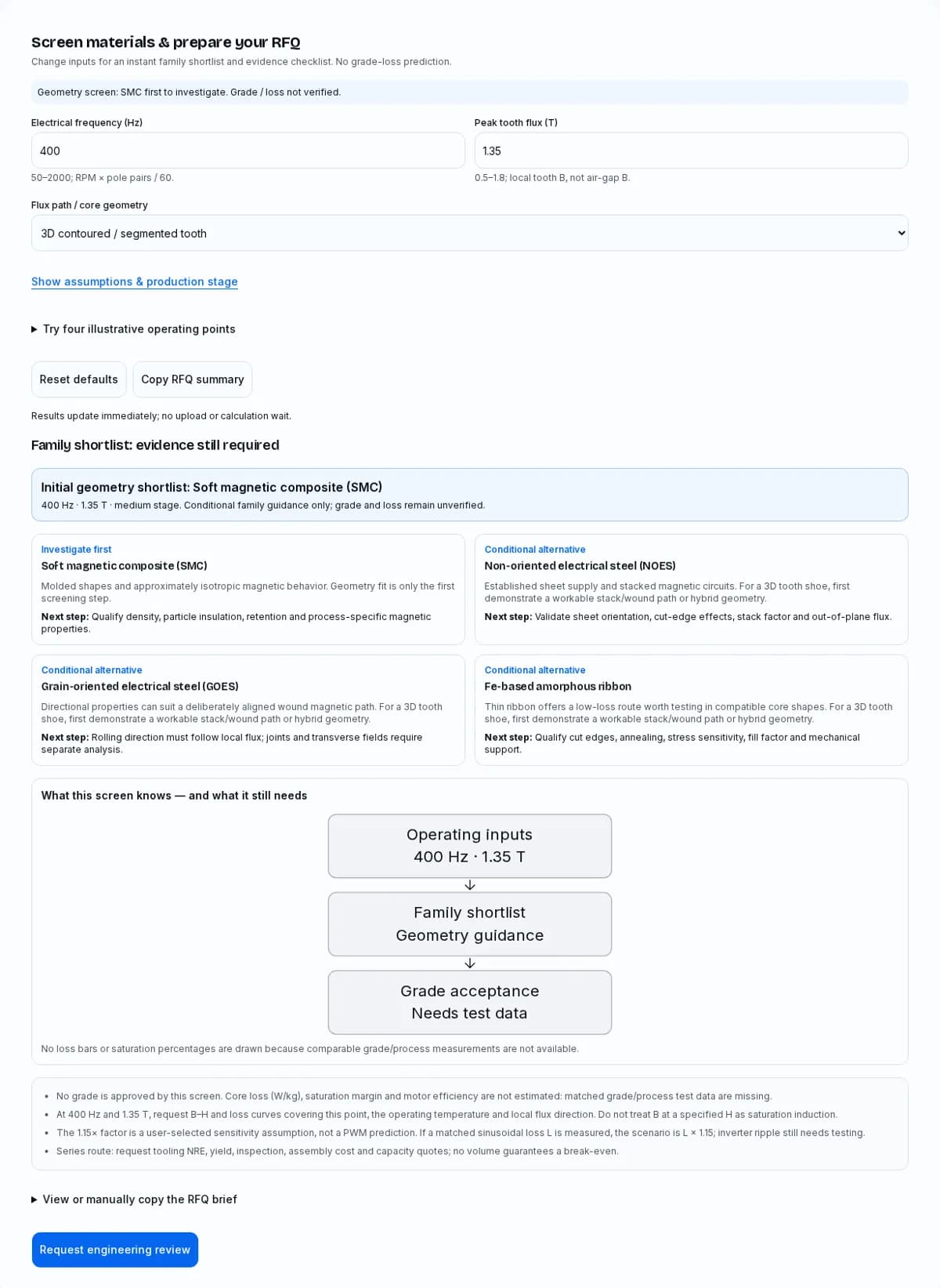
Screen materials & prepare your RFQ
Change inputs for an instant family shortlist and evidence checklist. No grade-loss prediction.
Family shortlist: evidence still required
Investigate first
Soft magnetic composite (SMC)
Molded shapes and approximately isotropic magnetic behavior. Geometry fit is only the first screening step.
Next step: Qualify density, particle insulation, retention and process-specific magnetic properties.
Conditional alternative
Non-oriented electrical steel (NOES)
Established sheet supply and stacked magnetic circuits. For a 3D tooth shoe, first demonstrate a workable stack/wound path or hybrid geometry.
Next step: Validate sheet orientation, cut-edge effects, stack factor and out-of-plane flux.
Conditional alternative
Grain-oriented electrical steel (GOES)
Directional properties can suit a deliberately aligned wound magnetic path. For a 3D tooth shoe, first demonstrate a workable stack/wound path or hybrid geometry.
Next step: Rolling direction must follow local flux; joints and transverse fields require separate analysis.
Conditional alternative
Fe-based amorphous ribbon
Thin ribbon offers a low-loss route worth testing in compatible core shapes. For a 3D tooth shoe, first demonstrate a workable stack/wound path or hybrid geometry.
Next step: Qualify cut edges, annealing, stress sensitivity, fill factor and mechanical support.
No loss bars or saturation percentages are drawn because comparable grade/process measurements are not available.
- No grade is approved by this screen. Core loss (W/kg), saturation margin and motor efficiency are not estimated: matched grade/process test data are missing.
- At 400 Hz and 1.35 T, request B–H and loss curves covering this point, the operating temperature and local flux direction. Do not treat B at a specified H as saturation induction.
- The 1.15× factor is a user-selected sensitivity assumption, not a PWM prediction. If a matched sinusoidal loss L is measured, the scenario is L × 1.15; inverter ripple still needs testing.
- Series route: request tooling NRE, yield, inspection, assembly cost and capacity quotes; no volume guarantees a break-even.
View or manually copy the RFQ brief
By AxialFluxCore · First recorded · Evidence reviewed .
Annual editorial review, with earlier corrections when supplier data or measurement scopes change. Public documents were checked on the review date; current availability, prices and part guarantees require supplier confirmation.
Evidence policy: linked manufacturer facts and publisher scopes are distinguished from editorial checklists. No measured customer case, fitted grade-loss database or motor efficiency guarantee is claimed.
Four decisions before selecting a grade
Geometry sets the first shortlist
Investigate SMC for contoured 3D teeth and NOES for a workable planar stack; retain alternatives until the real flux path is reviewed.
Evidence / scope: Höganäs: Somaloy SMC technology · JFE: Super Core magnetic property curves (PDF)
Loss needs matched measurements
No universal 400–600 Hz crossover is established. Compare the same f, B, waveform, temperature and processing state.
Evidence / scope: JFE: Super Core magnetic property curves (PDF) · IEC 60404-6:2018 RLV
Strength and B–H terms must stay distinct
TRS is not tensile strength, and induction at a stated H is not Bs. Use the right test quantity for the design question.
Evidence / scope: Höganäs: Somaloy 3P material data (PDF) · IEC 60404-4 consolidated edition (2008)
A family is not an approved stator
Qualify retention, cooling, manufacturing yield and delivered cost before grade release. Production volume alone proves no payback.
Basis: editorial engineering checklist; no measured performance or universal limit asserted.
1. Start with the local flux path
Axial motor topology does not by itself choose the core material.
Map the magnetic vector through tooth stems, shoes, joints and any back iron before choosing a family. A flat motor can still use carefully oriented laminations; conversely, a three-dimensional shoe may be difficult to realize with a single stack orientation. SMC is a useful starting point where molding and multidirectional flux solve a concrete geometry problem.
The tool therefore shortlists SMC for the 3D option and NOES for the planar option. This is an explicit editorial rule. It neither excludes alternative architectures nor approves an exact commercial grade. Compare manufacturable geometry and assembled mass before optimizing a catalog loss number.
Evidence / scope: Höganäs: Somaloy SMC technology
Qualitative screening dimensions; none of these cells is a performance guarantee.
| Family | Useful starting point | Evidence still needed |
|---|---|---|
| SMC | Contoured tooth shoes and multidirectional paths | Density, insulation, B–H and process-specific loss |
| NOES | Flux predominantly within stacked sheet planes | Gauge, orientation, edge condition, stack factor |
| GOES | A wound path deliberately aligned with rolling direction | Local vector alignment, joints and transverse excitation |
| Amorphous ribbon | Compatible wound/cut forms with low-loss objectives | Stress/anneal state, cutting, support and fill factor |
Evidence / scope: Höganäs: Somaloy SMC technology · JFE: Super Core magnetic property curves (PDF) · Metglas: amorphous transformer core brochure (PDF)
Next action: Mark local flux directions on the CAD sections and review each production route.
2. Read the screening result correctly
A shortlist identifies what to investigate; it is not a material certificate.
Frequency and peak tooth flux are recorded in the brief so the supplier can return relevant evidence. They do not create a loss estimate from nothing. Production stage changes the procurement checklist, while the optional factor expresses a user assumption for sensitivity discussion. None of these inputs supplies missing grade measurements.
No numerical suitability score is published. A weighted score can hide a failing constraint, such as a poor rolling-direction match or an unsupported tooth. Review each condition separately and leave missing quantities explicitly unknown. The conditional alternatives remain visible so a topology change can still be considered.
Basis: editorial engineering checklist; no measured performance or universal limit asserted.
Unknown does not mean zero. The shortlist is an editorial geometry rule, not a trained or calibrated model.
| Question | Known | Unknown / next evidence |
|---|---|---|
| Frequency and tooth B | Entered by the user | Local waveform, duty and temperature |
| Geometry shortlist | SMC first for 3D; NOES first for planar | Actual manufacturability and magnetic alignment |
| Core loss (W/kg) | No matched data loaded | Supplier curves and finished-core measurement |
| Saturation margin | Not calculated | Full B–H curve at working conditions |
| Unit economics | Production stage only | Quote, NRE, yield, assembly and annual demand |
Basis: editorial engineering checklist; no measured performance or universal limit asserted.
Next action: Use the output as a request for evidence, then compare qualified grades.
3. SMC properties belong to a grade and process
Do not transfer one specimen’s properties to every powder compact.
The bounded example below illustrates why powder name alone is insufficient: additive, pressing and heat treatment belong with the reported properties. The strength measures also answer different load questions. A procurement drawing should identify the intended process and test basis rather than copy a generic SMC property range.
The supplier PDF includes multiple sheets. Use the heading and processing row of the exact sheet, and obtain current confirmation for the intended part. Prototype machining, surface finishing and assembly may change the result relative to a standard specimen. The calculator uses none of these values as a universal saturation or loss constant.
Evidence / scope: Höganäs: Somaloy 3P material data (PDF)
Somaloy 700HR 3P, 600 MPa compaction, 80°C die, 530°C steam treatment; specimen values, not finished-stator guarantees. Refer to the exact sheet in the linked PDF.
| Property | Published value | Interpretation |
|---|---|---|
| Density | 7.40 g/cm³ | Specific process; not a universal minimum |
| B at H = 10,000 A/m | 1.53 T | An operating point, not saturation induction |
| Transverse rupture strength | 130 MPa | Different test from tensile strength |
| Tensile / yield strength | 55 / 55 MPa | Do not substitute TRS in a tensile check |
| Thermal conductivity | 30 W/(m·K) | Not the conductivity of a potted assembly |
Evidence / scope: Höganäs: Somaloy 3P material data (PDF)
Next action: Request the exact grade sheet and processing condition with the sample quotation.
4. There is no universal SMC–NOES crossover
Frequency alone cannot establish a winning material.
Core loss depends on induction, waveform, direction, temperature, specimen size and manufacturing state. Two catalog curves can cross for one set of conditions and reverse elsewhere. A fixed claim that SMC beats all thin steel above 400–600 Hz is not supported by the evidence presented here.
Build a comparison grid over the duty points that drive heating and energy use. Request common test conditions and disclose any unavoidable differences. Use the JFE catalog as a grade-specific curve source, not a surrogate for an assembled AFPM stator under inverter excitation. Check whether the quoted gauge, alloy and condition actually match the candidate supplied.
Evidence / scope: JFE: Super Core magnetic property curves (PDF) · IEC 60404-6:2018 RLV
A lower catalog value proves little if the excitation and specimen conditions differ.
| Match this variable | Why it changes the comparison | RFQ request |
|---|---|---|
| f and peak B | Loss depends on both | A curve/grid around every critical operating point |
| Waveform and flux direction | Sine, PWM and rotation are different | Test waveform and local vector history |
| Temperature | Material response changes with temperature | Hot and nominal-condition data |
| Specimen / processing | Ring, sheet and cut tooth differ | As-processed finished-part correlation |
| Mass basis | W/kg and total W answer different questions | Core mass and loss per active material mass |
Evidence / scope: IEC 60404-2:1996 + AMD1:2008 · IEC 60404-6:2018 RLV · JFE: Super Core magnetic property curves (PDF)
Next action: Ask each supplier for comparable f/B data and a finished-core correlation plan.
5. Separate saturation from a B–H operating point
A single B value at a specified H does not define available torque headroom.
A saturation-margin display requires a defensible material limit and a definition of local operating flux. A supplier’s B at a specified magnetizing field is not automatically Bs. Maximum permeability is also a point-dependent property, not a constant that can be used throughout the magnetic circuit.
At high requested tooth induction, obtain the full working B–H curve and include joints, air gaps, temperature and section changes in the magnetic model. If the curve does not cover the point, do not extrapolate an approved grade or apply an arbitrary penalty that still leaves it ranked as usable. This tool explicitly leaves that approval unresolved at every input point.
Evidence / scope: IEC 60404-4 consolidated edition (2008)
The model deliberately leaves saturation margin unknown.
| Quantity | Meaning | Misuse to avoid |
|---|---|---|
| B(H) | Induction at a specified field strength | Calling one B(H) point the saturation value |
| Bs / saturation induction | A material-specific limiting magnetic quantity | Using a family-wide constant for every process |
| μmax | Maximum permeability at its own field point | Treating it as constant operating permeability |
| Local tooth B | Flux density in a specific magnetic section | Replacing it with average air-gap B |
Evidence / scope: IEC 60404-4 consolidated edition (2008) · Höganäs: Somaloy 3P material data (PDF)
Next action: Validate the requested local B with grade-specific curves and the actual magnetic circuit.
6. Prove a production route early
A magnetic advantage is useful only if the geometry can be manufactured and assembled.
For a compacted tooth, check pressing direction, ejection, transitions, minimum features and access for tooling. For a laminated or wound segment, review sheet orientation, stack height, cut edges, bonding, joints and insulation. A visually simple shoe can still require difficult tooling or secondary operations.
Prototype routes should preserve the features that matter to the later magnetic test. A machined sample is not automatically equivalent to a pressed production part; a hand-bonded stack is not automatically equivalent to a production bonded stack. Record the process differences so the next design decision is based on representative evidence.
Evidence / scope: Höganäs: Somaloy SMC technology · JFE: Super Core magnetic property curves (PDF)
Editorial route checklist. Tool release, feature size and coating survival need a drawing review.
| Route | Risk | Verification |
|---|---|---|
| SMC pressing | Density variation, ejection cracks, tool access | Press-direction review and representative samples |
| Machined SMC prototype | Surface smearing may bridge insulation | Before/after loss and surface inspection |
| Cut / stacked NOES | Cut-edge stress, burrs, bonding and stack height | Sample stacks using the intended route |
| Wound GOES / ribbon | Alignment, cut joints, residual stress | Finished segment test and assembly trial |
Evidence / scope: Höganäs: Somaloy SMC technology · JFE: Super Core magnetic property curves (PDF) · Metglas: amorphous transformer core brochure (PDF)
Next action: Order representative samples and an agreed inspection/test plan before committing production tooling.
7. Review retention, potting and cooling as an assembly
A material data sheet cannot qualify the stator structure.
Tooth support must carry the actual magnetic pull, torque reaction and vibration loads. Potting can contribute to retention and heat transfer, but it does not replace a load-path analysis. Specify the resin, cure process, bond preparation, void criteria and aging evidence; avoid declaring that a particular resin or tie-rod arrangement is mandatory for all motors.
Thermal conduction is also an assembly property. Sheet-plane orientation, interfaces, adhesive, porosity, contact pressure and coolant access can dominate the route. Do not assign one bulk conductivity to every potted stator or use an unexplained shear-stress formula as a life prediction.
Basis: editorial engineering checklist; no measured performance or universal limit asserted.
Design checks to agree for the actual assembly; no universal resin formulation or stress limit is asserted.
| Risk | Evidence to request | Possible mitigation |
|---|---|---|
| Tooth bending / pull-out | Load cases, fatigue and support path | Positive retention or qualified encapsulation |
| Cure shrinkage / CTE mismatch | Resin modulus, CTE and bond data over temperature | Qualified cure, interface geometry or compliant layer |
| Thermal bottleneck | Directional stack and interface thermal tests | Cooling path redesign and void control |
| Electrical insulation | Creepage, dielectric and aging requirements | Insulation system validation after thermal cycling |
Basis: editorial engineering checklist; no measured performance or universal limit asserted.
Next action: Validate mechanical, thermal and dielectric performance on the intended assembly.
8. Compare delivered cost and tooling risk
Volume is one input; break-even requires comparable quotes.
No public evidence here establishes a universal mold price, cycle time, scrap rate or production-volume threshold. Economics depend on geometry, cavities, press capacity, yield, secondary operations, assembly and inspection. A low raw-material loss can be offset by expensive handling or a low first-pass yield.
For two routes with fixed costs F₁/F₂ and variable delivered costs c₁/c₂, compare F + N × c over the same quantity and acceptance boundary. A positive break-even N = (F₁ − F₂)/(c₂ − c₁) exists only when the denominator and route assumptions make sense. Include tooling life and capacity before treating that quantity as a purchasing decision.
Basis: editorial engineering checklist; no measured performance or universal limit asserted.
No current prices or universal production-volume break-even are available. Obtain comparable supplier quotations.
| Cost block | SMC route question | Laminated / wound question |
|---|---|---|
| NRE and samples | Dies, press trials, density qualification? | Cutting/stacking fixtures and winding tools? |
| Part conversion | Cycle, cavities, yield and secondary operations? | Nesting, burr control, bonding and scrap recovery? |
| Assembly | Retention, coils and potting labor? | Stack factor, joints and handling yield? |
| Delivered cost | Inspection, packaging, freight and lead time? | Same boundary and delivery quantity? |
Basis: editorial engineering checklist; no measured performance or universal limit asserted.
Next action: Obtain NRE and delivered-part quotations for the same drawing and acceptance criteria.
9. Match the test method to the question
DC magnetization, AC permeability and specific loss are different acceptance metrics.
The public publisher scopes below help select a discussion with a laboratory. They are not a substitute for the full normative documents. Identify specimen geometry, waveform, frequency range, mass basis and uncertainty in the purchase specification. Agree how a specimen result will be related to an assembled core.
A standard number alone is insufficient: a DC method does not supply inverter-fed loss, and an AC permeability measurement does not automatically give a loss acceptance result. For high-frequency steel testing, ask the laboratory to identify an applicable method rather than assume that a power-frequency sheet test covers the operating point.
Evidence / scope: IEC 60404-2:1996 + AMD1:2008 · IEC 60404-3:2022 · IEC 60404-4 consolidated edition (2008) · IEC 60404-6:2018 RLV · ASTM A772/A772M-00(2022)
Public publisher summaries checked on the review date. Purchase/review the full applicable standard and agree deviations with the laboratory.
| Reference | Publicly stated scope | Limit |
|---|---|---|
| IEC 60404-2 | Epstein-frame steel sheet/strip, AC up to 400 Hz | Not automatic coverage of every high-frequency point |
| IEC 60404-3:2022 | Single-sheet electrical steel, power frequencies | Does not itself validate PWM correction |
| IEC 60404-4 | DC magnetic properties | Does not supply AC core loss |
| IEC 60404-6 | Other soft magnetic materials, ring samples, 20 Hz–100 kHz | Excludes electrical steels and soft ferrites |
| ASTM A772/A772M | AC impedance permeability, sinusoidal current | Not a substitute for a loss specification |
Evidence / scope: IEC 60404-2:1996 + AMD1:2008 · IEC 60404-3:2022 · IEC 60404-4 consolidated edition (2008) · IEC 60404-6:2018 RLV · ASTM A772/A772M-00(2022)
Next action: Put the applicable method, edition, test point and acceptance limit in the RFQ.
10. Turn the screen into a sourcing package
The export preserves inputs and states what remains unverified.
The generated brief includes electrical frequency, local peak tooth induction, geometry, production stage and the assumed sensitivity factor. It intentionally includes no approved grade or predicted W/kg. Add a drawing revision and actual quantities before submitting it through the inquiry route.
Attach the speed/pole-pair relationship, duty points and waveform requirements so suppliers can challenge inconsistent inputs. Ask for deviations explicitly: a supplier should identify which values are catalog typicals, which are tested on samples, and which can be guaranteed at acceptance. Keep the designer responsible for system limits and have the supplier confirm manufacturing capability.
Basis: editorial engineering checklist; no measured performance or universal limit asserted.
The tool exports preliminary operating inputs; these items still need completion.
| Package | Minimum content | Acceptance owner |
|---|---|---|
| Operating point | RPM, pole pairs, tooth B, duty, temperature, inverter waveform | Motor designer |
| Geometry | CAD revision, flux direction, stack/press orientation, critical datums | Designer + manufacturing supplier |
| Magnetic | Grade/process, test method, f/B grid, loss and B–H acceptance | Designer + test laboratory |
| Assembly | Retention loads, cooling, resin and insulation requirements | Assembly engineering |
| Commercial | Sample/annual quantity, NRE, inspection, yield, lead time | Procurement + supplier |
Basis: editorial engineering checklist; no measured performance or universal limit asserted.
Next action: Copy the brief, complete the missing requirements and request a drawing review.
11. What a Bertotti-style model would require
An equation is not a calibrated materials database.
A common separation form is P = kh·f·B^α + ke·f²·B² + ka·f^1.5·B^1.5. Coefficients depend on the fit, units, specimen, waveform and valid f/B domain. This page presents the form as a method explanation; it does not claim to supply fitted coefficients for commercial grades.
A useful fit requires measured data, a declared fitting method and independent checks over its intended domain. Rotational fields, cutting damage, joints and PWM minor loops may require different treatment. The optional factor in the tool is only Lscenario = Lmeasured × factor; without a matched measured L, no numeric loss is returned.
Evidence / scope: Research article (2024): A Practical Hybrid Hysteresis Model for Calculating Iron Core Losses in Soft Magnetic Materials
Next action: Use measured curves or a validated fit with a documented domain and uncertainty.
12. PWM and duty-cycle evidence
A single multiplier cannot resolve inverter-fed motor loss.
Carrier frequency alone does not define the flux ripple in a tooth. DC-link voltage, modulation, current ripple, local inductance and control strategy matter. A sensitivity factor can organize a what-if discussion, but it cannot prove a material-specific benefit or a motor efficiency percentage.
Evaluate thermal duty separately from peak capability. A short high-B event and sustained high-speed operation can impose different constraints. Request local transient magnetic results and a test plan that relates inverter-fed measurements to the sinusoidal material data. Report the waveform and temperature with any claimed loss reduction.
Basis: editorial engineering checklist; no measured performance or universal limit asserted.
Next action: Record the inverter conditions and test representative continuous and transient duty points.
13. GOES and amorphous ribbon are conditional alternatives
Low catalog loss does not settle AFPM geometry compatibility.
GOES requires deliberate alignment of the rolling direction with the local magnetic path. A planar or tape-wound shape by itself does not establish that alignment at slots, shoes, joints and return paths. Compare the actual directional model before accepting a wound route.
The Metglas brochure reports typical 2605SA1 saturation induction of 1.56 T, resistivity of 1.3 µΩ·m and magnetostriction of 27 ppm. These are material data from a transformer-oriented publication, not proof of AFPM efficiency. Annealing, stress, cutting and retention still require application-specific verification.
Evidence / scope: Metglas: amorphous transformer core brochure (PDF)
Next action: Request a magnetic-direction map and a representative assembled segment for testing.
14. When a hybrid core is worth investigating
Combining materials adds interfaces that also need qualification.
A laminated stem with an SMC shoe can separate a primarily planar section from a spreading field region. This is an architecture option, not an automatic optimum. The interface introduces gap, alignment, adhesive, thermal and retention questions that a family-level tool cannot resolve.
Compare the hybrid with both complete alternatives using the same magnetic loading, total active mass, cooling boundary and assembly cost. Document which constraint the hybrid solves. If that improvement depends on a small interface gap or tight shoe position, include those tolerances and inspectability in the manufacturing review.
Basis: editorial engineering checklist; no measured performance or universal limit asserted.
Next action: Advance a hybrid only when its specific benefit survives interface and assembly analysis.
15. Heat treatment is grade-specific
Do not prescribe one atmosphere for all SMC grades.
The cited 3P sheet specifies steam treatment for its stated process. That directly contradicts a blanket rule that all SMC must be annealed in dry inert gas. Different insulation systems and additives require their own validated process windows.
Use the current supplier process specification and track furnace conditions, handling and post-treatment inspection with the batch. Do not transfer temperature, atmosphere or machining advice from another powder family. If a subcontractor proposes a change, qualify its magnetic, dimensional and mechanical effects before accepting the parts.
Evidence / scope: Höganäs: Somaloy 3P material data (PDF)
Next action: Have the powder/part supplier confirm the exact treatment and permitted secondary operations.
16. Release only after the evidence gaps close
Move from a conditional family to a traceable grade and acceptance record.
A release package should connect the drawing revision, material/process revision, test records and assembly validation. Resolve any mismatch between catalog coupons and supplied parts. Where public evidence is insufficient, mark it pending and assign an owner rather than replacing the gap with an attractive score or chart.
The six examples below are hypothetical screening exercises. They demonstrate consistent speed/frequency inputs and the next evidence needed; they are not customer projects, measured efficiencies or certified application claims. Re-run the screen if the geometry or duty changes, then review the evidence again before purchasing.
Basis: editorial engineering checklist; no measured performance or universal limit asserted.
Next action: Require signed-off magnetic, mechanical, thermal, dimensional and commercial criteria.
Reproduce a material screening example
Run the default 400 Hz, 1.35 T, 3D geometry, medium production-stage example with a 1.15× assumed sensitivity factor. Change geometry to a planar stack: the initial investigation moves from SMC to NOES. Neither result approves a grade or predicts W/kg.
Six illustrative screening scenarios
Hypothetical inputs and next decisions, not real customer projects or measured outcomes. Frequency = RPM × pole pairs / 60.
3D segmented propulsion study
2,400 RPM × 20 pole pairs (40 poles) / 60 = 800 Hz · 1.15 T tooth B
Process: Investigate SMC shape feasibility; compare a realizable stacked alternative.
Screening outcome: A geometry shortlist only. Hot loss, support loads and application qualification remain pending.
Series traction drive study
1,500 RPM × 16 pole pairs (32 poles) / 60 = 400 Hz · 1.45 T tooth B
Process: Review compaction tooling, local B–H behavior and retention before requesting series quotes.
Screening outcome: No torque density, efficiency or cost improvement is claimed.
Planar rotary-table study
300 RPM × 12 pole pairs (24 poles) / 60 = 60 Hz · 1.6 T tooth B
Process: Start with NOES geometry; verify the requested tooth B and cut-stack condition.
Screening outcome: Holding torque and thermal capability need a magnetic circuit and duty test.
High-frequency compressor study
45,000 RPM × 2 pole pairs (4 poles) / 60 = 1500 Hz · 0.85 T tooth B
Process: Compare thin steel and compatible ribbon forms at matching f/B and stress conditions.
Screening outcome: A catalog low-loss material does not establish assembled motor efficiency.
Auxiliary drive study
3,600 RPM × 10 pole pairs (20 poles) / 60 = 600 Hz · 1.48 T tooth B
Process: Review SMC versus an alternative topology using the same continuous thermal boundary.
Screening outcome: Grade loss, hot-spot temperature and tooling economics are unknown until tested/quoted.
Compact generator study
6,000 RPM × 8 pole pairs (16 poles) / 60 = 800 Hz · 1 T tooth B
Process: Compare planar NOES with aligned wound/ribbon alternatives; request waveform data.
Screening outcome: No airborne certification, mass reduction or measured endurance is implied.
Technical & sourcing FAQ
Tool and evidence
Does the tool approve a commercial grade?
No. It uses an explicit geometry rule to shortlist material families and exports an input brief. Grade acceptance needs process-specific magnetic data and assembly validation.
Why is no W/kg prediction displayed?
Comparable grade/process measurements or validated fitted coefficients are missing. Showing an invented value would obscure the main evidence gap. Request loss curves at your f, B, waveform and temperature.
What does the loss sensitivity factor mean?
It is an assumed scenario multiplier, default 1.15×. If a matched sinusoidal loss L has been measured, the scenario is L times the factor. It is not a prediction of PWM loss or a material-specific correction.
How do I recover from an empty or invalid input?
Correct the field using the stated range or select Reset defaults. Results and export pause while any input is invalid. You can still contact engineering with the information you have.
Can I use the page without JavaScript or clipboard access?
Without scripts, read the static default screen and evidence report, then use the email/contact path. If clipboard access fails, expand the RFQ brief and select its text manually.
Magnetic comparison
Does SMC always win above 400–600 Hz?
No universal crossover is established here. Grade, induction, geometry, waveform and processing can change the comparison. Match test conditions before drawing a frequency-based conclusion.
Is every axial flux motor a 3D SMC application?
No. Evaluate local flux direction through the manufacturable core. A suitable lamination or wound layout can remain a candidate even when the overall machine is axial flux.
Is B at 10,000 A/m the same as Bs?
No. It is one point on a magnetization curve. Do not use it as a universal saturation constant or derive an approved torque margin from it.
Evidence / scope: IEC 60404-4 consolidated edition (2008)
Can I enter air-gap induction as peak tooth induction?
Only if analysis has shown they are equal for the relevant section, which should not be assumed. The tool expects the local tooth flux density at the operating point.
How do I convert speed to electrical frequency?
Electrical frequency in Hz equals RPM times pole pairs divided by 60. For example, 2,400 RPM with 20 pole pairs (40 poles) is 800 Hz. Pole count and pole-pair count differ by a factor of two.
Material alternatives
When should I investigate NOES?
Start with NOES where the intended flux can remain predominantly within the sheet planes and a practical stack exists. Verify the exact gauge, alloy, cutting process, bonding and duty.
Does a tape-wound shape automatically suit GOES?
No. The rolling direction must align with the important local flux paths. Joints and transverse components can undermine the benefit; request directional analysis.
Does the Metglas brochure prove high AFPM efficiency?
No. It provides material information for transformer-oriented use. An AFPM result also depends on shaping, stress, winding, magnets, drive and cooling; no motor efficiency is inferred here.
Evidence / scope: Metglas: amorphous transformer core brochure (PDF)
Are hybrid SMC/lamination cores automatically better?
No. A hybrid may solve a geometry constraint but adds joints and assembly tolerances. Compare total loss, mass, heat flow and delivered cost at the same duty.
Manufacturing and sourcing
Must all SMC be heat-treated in inert gas?
No. Follow the exact grade/process specification. The referenced Somaloy 3P example specifies steam, so a blanket inert-atmosphere rule would be incorrect.
Evidence / scope: Höganäs: Somaloy 3P material data (PDF)
Can a machined SMC sample represent production?
It can support development only if process differences are documented and tested. Check surface insulation and magnetic properties after machining and compare with representative pressed parts.
Is TRS an allowable tensile stress?
No. Transverse rupture strength and tensile strength come from different tests. Apply the appropriate measured property, load case and design criteria to the supported assembly.
Does potting alone qualify tooth retention?
No. Verify load paths, resin/interface properties, cure and aging behavior. Include mechanical, thermal and dielectric tests on the intended assembly.
What production volume guarantees tooling payback?
None is established here. Compare actual NRE plus delivered unit cost over the same quantity, yield, inspection and assembly boundary. The production-stage input only changes the sourcing checklist.
What should I send for an engineering review?
Send the generated brief plus CAD revision, speed/pole pairs, duty and temperature, inverter conditions, quantities and acceptance criteria. Ask the supplier to separate typical data from guaranteed limits.
Primary sources & evidence limits
Checked 2026-11-03. Source scopes describe what each document supports. They do not validate every editorial recommendation, commercial grade or assembled motor. Public standard abstracts were reviewed; full normative compliance is not certified by this page.
Research article (2024): A Practical Hybrid Hysteresis Model for Calculating Iron Core Losses in Soft Magnetic Materials
Primary research discussing hysteresis, classical and excess loss separation. Supports the model structure, not fitted coefficients for AFPM grades or motor validation.
Höganäs: Somaloy SMC technology
Primary manufacturer overview: 3D magnetic properties and net-shape production. Does not establish a universal loss crossover or cost.
Höganäs: Somaloy 3P material data (PDF)
Grade/process-specific specimen data. See the sheet headed “Somaloy 700HR 3P — 600 MPa”. B at a stated H is not Bs; no fitted coefficients from this sheet are used by the tool.
JFE: Super Core magnetic property curves (PDF)
Grade-specific curves for 10JNEX900, 10JNHF600 and 20JNHF1300. Request matching cut-part and temperature data before motor design.
Metglas: amorphous transformer core brochure (PDF)
2605SA1 typical material properties, not an AFPM motor efficiency test. Values in the brochure are not guaranteed.
IEC 60404-2:1996 + AMD1:2008
Epstein-frame sheet/strip measurement; published AC scope extends to 400 Hz. This is a method, not a grade approval.
IEC 60404-3:2022
Single-sheet measurement of electrical steel at power frequencies; does not validate a universal high-frequency motor correction factor.
IEC 60404-4 consolidated edition (2008)
DC properties by ring/permeameter methods. DC magnetization data alone do not predict AC loss.
IEC 60404-6:2018 RLV
Ring-specimen AC methods, 20 Hz–100 kHz, for soft magnetic materials other than electrical steels and soft ferrites. Check the applicable amendment in your test agreement.
ASTM A772/A772M-00(2022)
Impedance permeability under sinusoidal-current excitation. It is not interchangeable with a specific-total-loss acceptance test.
Bring the operating point and drawing to review
Send the brief plus CAD revision, duty, inverter conditions, quantities and acceptance criteria. Ask which grade/process data and representative tests are available before finalizing a material.
Direct contact: [email protected]