
Heat Treatment and Annealing Atmosphere for SMC Axial Flux Stator Cores: Lubricant Burnout, Lattice Strain Relief, Dielectric Integrity, and Sourcing Verification
Compare SMC stator heat treatment, lubricant burnout and annealing atmospheres. Use grade-specific evidence and a sourcing checklist to prepare your DFM review.
Decision-level summary: SMC axial flux stator heat treatment must reduce compaction-induced lattice strain while preserving electrical insulation between iron particles. Select the atmosphere and temperature from the exact powder grade and additive specification; nitrogen, air and steam are different processing routes. Lubricant removal must be qualified for the component section, furnace loading and exhaust arrangement. For sourcing, require a revision-controlled recipe, representative temperature records, companion magnetic specimens and agreed mechanical and dimensional acceptance tests. A low DC coercivity or a clean-looking surface alone cannot demonstrate acceptable AC core loss or winding integrity.
Published and reviewed: November 13, 2026. Scope: Global B2B motor engineering, powder metallurgy processing and supplier quality for soft magnetic composite (SMC) stator teeth and cores in axial flux permanent magnet machines. This guide addresses processing selection and procurement evidence. Winding insulation, potting, assembled motor cooling and application certification need separate qualification. It synthesizes manufacturer guidance into an engineering review framework; it does not report first-party furnace trials or measured production performance. Numerical acceptance limits must come from the selected material, drawing and approved pilot results.
Transitioning from magnetic simulation to compacted prototype cores? Request a drawing-led engineering review with your tooth geometry, operating frequencies, core loss budget and mechanical loads. Our compaction tooling DFM guide covers tooling considerations, while manufacturing quality controls outline the verification evidence to agree before ordering.
1. Metallurgical Dilemma: Lattice Strain Relief vs. Particle Insulation
Compacting insulated iron powder creates a dense, shaped component, but plastic deformation also introduces residual stress and crystal defects. These can impede magnetic domain wall motion, increasing the field required to reverse magnetization. Heat treatment can relieve some of this strain and improve magnetic behavior. The useful treatment window is constrained by the insulation, additive system and permissible dimensional change.
An SMC core relies on electrical separation between particles to restrict inter-particle eddy currents. Damage to that separation can create longer conductive paths through the compact. Lower hysteresis loss after a hotter treatment therefore does not establish lower total loss at the motor's operating frequency. Mechanical strength and magnetic loss must be assessed together, using specimens with a documented processing history.
Do not infer coating chemistry or an organic resin binder simply from a Somaloy performance designation. Proprietary grades and additives require their own documentation. Likewise, a conventional electrical steel annealing cycle cannot be transferred to an insulated powder compact merely because both materials contain iron. The objective is compatible stress relief, not maximum furnace temperature or conventional structural-part sintering.
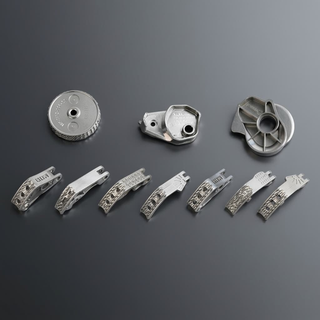
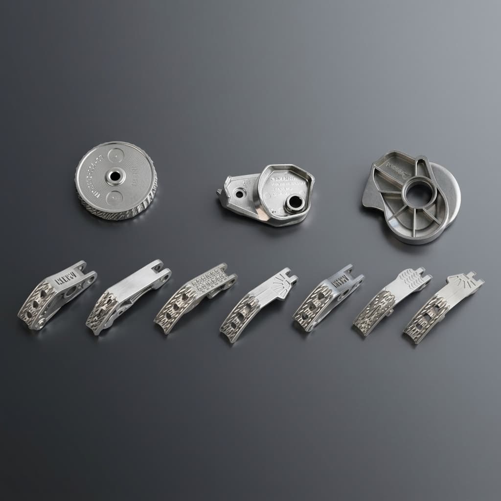
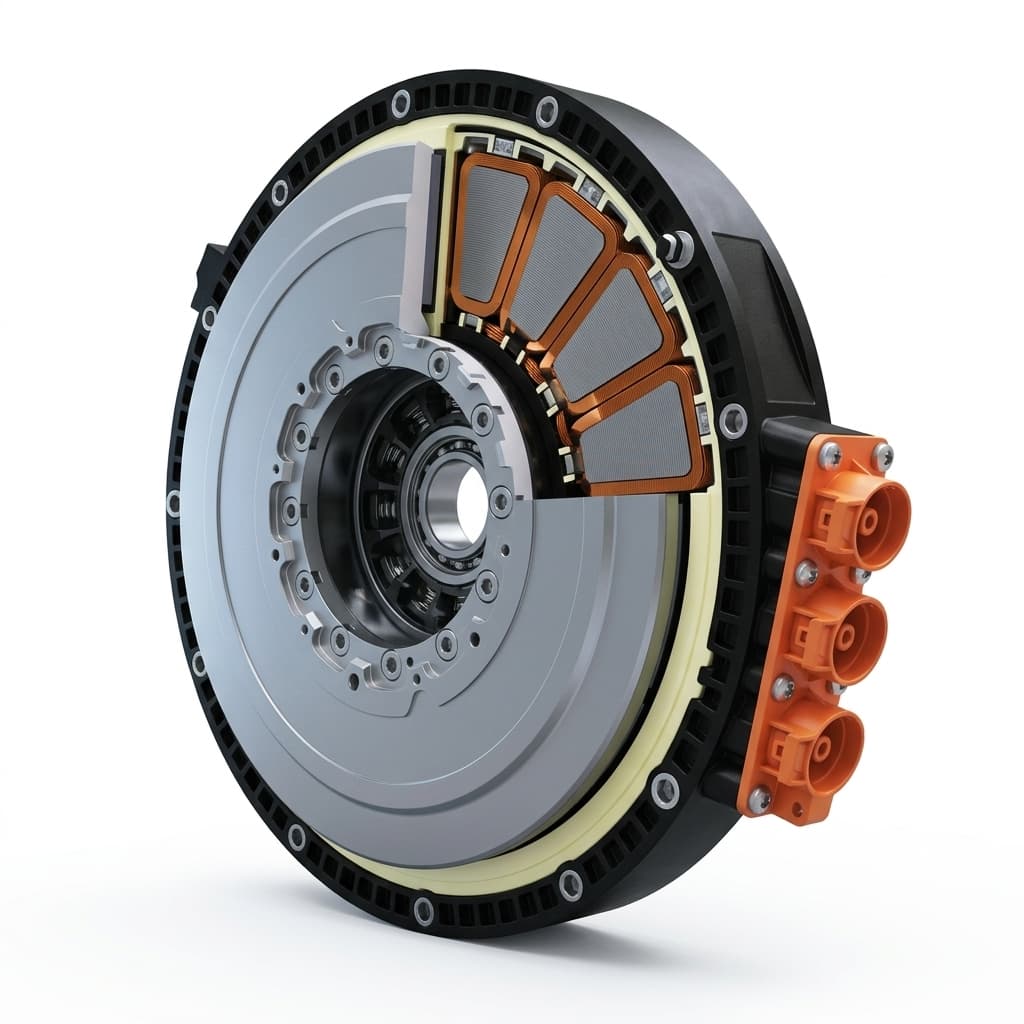
Figure 1: Illustrative component render, not a photograph of a heat-treatment run. Shape and surface appearance do not establish powder identity, insulation condition or magnetic performance.
Before requesting a quotation, identify the complete material designation, particle-size variant, lubricant/additive package and technical data revision. Ask whether the proposed cycle is the powder manufacturer's documented route or a supplier-developed alternative. An alternative requires representative qualification evidence rather than a verbal statement that it is equivalent.
2. Two Processing Objectives: Lubricant Removal and Stress Relief
Lubricant helps compaction and ejection, but its removal or transformation must be managed during subsequent heating. Decomposition products need an appropriate path out of the compact and furnace. Depending on the additive and atmosphere, removal can involve evaporation, decomposition and oxidation. A nitrogen sweep alone does not guarantee complete burnout, and an air treatment is not automatically appropriate for every coating.
Do not prescribe one preheat temperature and dwell for all SMC teeth. Thick sections, loading density and different lubricant systems can change the required profile. Ask for the additive supplier's guidance and evidence that the furnace cycle works at the proposed production throughput. A schedule developed on a lightly loaded prototype tray may behave differently on a fully loaded belt.
Figure 2: Qualification sequence. A separate removal stage may be appropriate, but the number of furnace zones, dwell times and temperatures must follow the approved material-specific process.
A useful supplier submission distinguishes furnace controller settings from component temperature. Record ramp rates, the point at which dwell timing starts, thermocouple placement, maximum loading, atmosphere transitions and cooling conditions. The relevant question is whether the representative part receives the required treatment throughout its section without exceeding the approved envelope.
For initial qualification, agree how incomplete removal will be detected. Potential evidence includes a mass-change study, suitable thermal analysis, residue inspection and chemistry measurements against an approved baseline. None of these alone proves magnetic suitability. Residual carbon includes contributions from the original material and process; a single universal carbon limit cannot establish complete lubricant removal across different formulations.
3. Annealing Atmosphere: Match the Exact Grade
The following are manufacturer-published examples, not interchangeable recipes or guaranteed properties for axial flux teeth:
- Somaloy 1P: Höganäs describes an economical baseline route using air, with a maximum heat-treatment temperature of 530°C. Its listed lubricant addition is typically 0.4–0.5% Kenolube P11. See the official 1P product guidance.
- Somaloy 3P: The manufacturer emphasizes mechanical strength and permeability and specifies a two-stage air-plus-steam treatment with a maximum of 530°C. This is more specific than simply calling it a steam anneal. See the official 3P product guidance.
- Somaloy 5P: The manufacturer positions this route for low core loss and specifies nitrogen treatment with a maximum of 650°C. See the official 5P product guidance.
A published maximum is a ceiling, not the nominal setpoint for every component. Obtain the current grade-specific processing sheet before specifying temperature tolerance, dwell or atmosphere transitions. The public summaries do not establish a universal dew point, oxygen concentration, gas flow or residual carbon acceptance limit.
What to record about furnace gas
For a nitrogen route, ask where oxygen and moisture are measured, how sensors are calibrated, how inlet gas quality differs from conditions near the loaded parts, and how an excursion is handled. Dew point reporting should identify measurement pressure and sampling location. A bottle purity certificate does not describe leakage or contamination inside the furnace.
For air or steam routes, intentional oxidizing conditions are part of the approved treatment. Applying an unrelated dry-nitrogen specification would change that process. Specify atmosphere transitions and condensation prevention according to the supplier's approved instructions. Do not substitute hydrogen-containing gas, vacuum or another atmosphere without written material compatibility and process qualification.
4. Sourcing Comparison: Evidence Required at Each Process Step
This table is a procurement decision framework. It contains no measured comparative property dataset, and its rows should not be used to rank suppliers by an assumed strength or loss value.
| Process choice or condition | What the supplier should provide | Buyer decision / limitation |
|---|---|---|
| As-compacted reference | Powder lot, density, geometry and untreated test results | Establish a baseline; do not infer finished-core performance |
| Grade-approved air treatment | Material instruction, loaded-part profile and atmosphere description | Confirm that air is specified for this exact material |
| Grade-approved air-plus-steam treatment | Transition sequence, steam control and representative mechanical results | Verify the complete sequence and handling requirements |
| Grade-approved nitrogen treatment | Temperature records, gas monitoring and magnetic test results | Check actual process conditions rather than nominal gas purity alone |
| Lubricant removal | Additive identity, ramp/loading study and agreed residue evidence | Qualify removal for the thickest relevant section |
| Vacuum or another proposed alternative | Written compatibility assessment and paired qualification results | Treat as a process change, not an automatic equivalent |
| Temperature or atmosphere excursion | Traceable affected lots, deviation record and disposition evidence | Hold affected material pending engineering review |
| Cooling, unloading and storage | Cooling profile, handling controls and post-process inspection | Confirm dimensions and surface condition at the specified inspection state |
Table 1: Eight process-review rows linking a manufacturing claim to the evidence needed for sourcing approval.
To compare quotations, send each supplier the same specimen definitions, operating points and acceptance plan. Otherwise, a low-loss ring made at one density and excitation condition may be compared with a mechanically stronger component made under entirely different conditions. Ask suppliers to separate catalogue values, pilot measurements and contractual production guarantees.
5. Core Loss Verification: Separate Material Screening from Motor Approval
Heat treatment can improve stress-sensitive magnetic properties while degrading electrical separation if it is incompatible with the coating. A supplier should therefore report AC loss at agreed flux density and frequency, not just DC coercivity, permeability or a single resistivity reading. Comparing several frequencies can help identify a changed loss trend, but it cannot uniquely diagnose a furnace defect.
The useful distinction is between hysteresis-related behavior and dynamic losses, including eddy currents. Simple frequency-scaling models can support an investigation when fitted within a documented range. They are not proof that loss will follow one universal curve or that a specific temperature is optimal for every grade. Avoid extrapolating a sinusoidal catalogue point directly to PWM excitation or a three-dimensional tooth flux pattern.
IEC 60404-6:2018 describes ring-specimen methods for AC magnetic characterization of covered soft magnetic materials, including powder composites, across 20 Hz to 100 kHz. Agree the applicable edition and amendments with the laboratory. The standard supplies a measurement framework; it does not set a universal maximum core loss for an axial flux stator.
For companion rings, record material lot, compaction direction and density, furnace position, thermal cycle, specimen dimensions, winding details and test temperature. Define flux waveform, peak flux density, frequency points, sample count and acceptance rule. Rings should travel with the production load where practical. Explain any density or thermal-history difference between rings and the actual teeth.
A reproducible illustration of loss-budget arithmetic is:
Illustrative design assumptions, not test results:
Finished SMC core mass = 1.20 kg
Allocated core loss = 48 W at one agreed operating point
Screening specific-loss budget = 48 W / 1.20 kg = 40 W/kg
That calculation helps frame a supplier discussion. It does not establish that a ring result of 40 W/kg predicts an assembled motor loss of 48 W: local flux variation, joints, temperature, harmonics and geometry still require assessment. Use component and motor validation to close that gap.
If your model and supplier data use different operating points, request a test-plan review with your DFM inquiry before comparing prices or committing to tooling.
6. Dimensional Stability and Axial Pole Face Flatness
Small dimensional changes can matter in an axial flux assembly, but there is no universal as-treated tolerance grade or pole-face flatness limit for all SMC teeth. Set requirements from the motor tolerance stack, rotor runout, bearing movement, thermal expansion and assembly method. Record whether a dimension applies to an individual tooth, a mounted segment or the completed stator ring.
During pilot qualification, measure representative parts before and after treatment using the same datums and inspection temperature. Include different locations across the furnace load and the geometries most likely to respond differently. The results establish the process allowance and inspection plan; do not assume that a nominally net-shape process eliminates finishing or sorting.
Review support trays, part orientation, loading spacing and cooling as potential contributors to variation. A tray that works for a short tooth may provide inadequate support or airflow for a different shape. If finishing is proposed, assess edge damage and possible conductive smearing alongside dimensional improvement. Check the final condition used for winding and assembly rather than releasing a part solely from an intermediate CMM report.
7. Quality Assurance and Drawing-Level RFQ Checklist
Use this checklist to obtain an executable agreement. Reference the approved process specification from the drawing instead of copying an unqualified generic furnace recipe onto every print.
- Material identity: Record the complete powder designation, additive package, technical data revision and permitted substitutions. Require traceability to the incoming powder lot.
- Lubricant removal: Define the qualified ramp, dwell or staged sequence, loading limits, exhaust controls and evidence used to demonstrate acceptable removal.
- Thermal envelope: Specify the approved part-temperature range, exposure time, monitoring locations and furnace uniformity evidence under representative loading.
- Atmosphere controls: Identify gas composition, transitions, measurement locations, calibration, agreed oxygen/moisture limits where relevant and excursion handling.
- Residue and chemistry: Agree the analytical method, sampling, baseline and acceptance criteria. Distinguish total carbon from residue attributable to processing.
- Mechanical integrity: Agree specimen geometry, test method and acceptance criteria, plus representative handling or winding trials. Coupon strength is not an allowable tooth design stress.
- Electrical separation: Define any bulk resistivity method, electrode arrangement, units, conditioning and baseline. Surface resistance and volume resistivity are different quantities.
- Magnetic acceptance: Specify companion ring traceability, excitation conditions, temperature, sample count, lot definition and loss limits supported by the application plan.
- Geometry and surface condition: Define datums, flatness, parallelism, edge condition, inspection state and sampling for the finished component.
- Change control: Require approval for changes to powder, additive, furnace, loading, supports or atmosphere. Define containment and requalification before affected lots are released.
For transverse rupture strength, do not treat a green-strength result as proof of finished-part strength. ASTM B528 addresses transverse rupture testing of sintered, including post-treated, powder-metallurgy specimens and states that TRS is not a design value. Since insulated SMC processing differs from conventional sintering, the laboratory must justify method applicability or agree a documented adaptation. Obtain the specimen and fixture details with the result.
For resistivity, request a method suitable for the compact's geometry and resistance range. A four-contact arrangement can reduce contact-resistance effects, but it still needs a valid geometry calculation and measurement uncertainty. Do not apply a generic metallic-conductor or plastics test designation without establishing suitability for the SMC specimen.
8. Failure Investigation: Use Symptoms to Plan Tests
A symptom narrows an investigation; it does not prove one cause. Preserve failed samples and process records before changing the recipe. The following sequence helps avoid correcting one property while damaging another.
- Excess core loss: First confirm waveform, flux density, frequency, temperature, density and specimen comparability. Then compare process logs and electrical/magnetic measurements with the qualified baseline. Change treatment only within the material-approved window.
- Blistering or delamination: Examine compaction history, ejection damage, additive removal, section thickness and loading. Cross-sections and controlled paired trials are more useful than assuming every crack came from trapped vapor.
- Tooth chipping during winding: Review corner condition, fixture support, wire path, insulation and dynamic loading alongside material integrity. A dark fracture surface alone cannot establish soot contamination or a quantitative strength loss.
- Oxide or discoloration: Compare the surface with the intended atmosphere and approved reference condition. Check gas records, moisture exposure and storage. Color alone is not a reliable acceptance test or a measure of internal insulation.
- Warpage or dimensional drift: Compare pre/post-treatment measurements, support conditions, furnace position and inspection setup. Separate part distortion from assembly or measurement effects before changing a temperature setpoint.
Document one proposed change and its acceptance evidence before running a controlled trial. Hold suspect lots until the agreed disposition is complete. Reheating is a process change requiring assessment; it is not an assumed repair for high loss, low strength or an atmosphere excursion.
9. Frequently Asked Questions
Can a standard mesh-belt furnace be used for SMC heat treatment?
Potentially, if it can reproduce the material-approved atmosphere, loaded-part temperature history, additive removal and cooling conditions. A furnace previously used for another powder-metallurgy process may need a contamination assessment and different controls. Qualify representative loads rather than approving equipment based on its maximum temperature rating.
Why not anneal SMC stator teeth like electrical steel laminations?
The inter-particle insulation is part of the SMC's electrical design. A cycle intended for uncoated metal or a different insulation system may damage that separation even if it reduces mechanical strain. Use the powder manufacturer's route and verify AC loss; there is no universal coating-breakdown temperature that replaces grade-specific instructions.
Are Somaloy 1P, 3P and 5P interchangeable temperature classes?
No. They identify manufacturer-defined performance and processing routes. Compare their documented atmosphere requirements, current material data and application evidence. The examples in Section 3 describe route boundaries; they do not establish equivalent strength, corrosion resistance, winding capability or motor efficiency for a chosen tooth design.
Is a dew point of minus 40°C mandatory for every SMC cycle?
No universal limit is established by the public product summaries cited here. Moisture control can be relevant to a nitrogen route, while an approved steam process deliberately uses water vapor. Agree limits and measurement conditions with the material and furnace suppliers for the selected process; avoid transplanting one gas specification to another route.
Can vacuum replace protective nitrogen?
Treat vacuum as a proposed alternative requiring written compatibility and qualification. Pressure changes additive removal and heat transfer, and the part's temperature history may differ from its furnace controller reading. A clean surface or a successful unrelated metal anneal is insufficient evidence of equivalent SMC magnetic and mechanical properties.
Does bulk resistivity prove winding dielectric integrity?
No. Bulk resistivity helps characterize conductive paths within the SMC material. Winding-to-core insulation performance depends on the wire enamel, liners or coatings, edge condition and assembly damage. Define electrical insulation tests for the wound component separately. Companion ring loss also supports material qualification rather than replacing a completed motor's insulation or thermal validation.
What should a buyer request before approving a production lot?
Request the traceable material and furnace records, agreed magnetic and mechanical test results, finished-part dimensional inspection and any deviation disposition. Establish sampling and rejection rules before production. A certificate saying only “heat treated to supplier standard” does not identify the evidence needed to release the batch.
10. Sources and Evidence Boundaries
Official sources checked for this review on November 13, 2026:
- Höganäs — Somaloy 1P: public material and processing summary.
- Höganäs — Somaloy 3P: public description of its air-plus-steam route.
- Höganäs — Somaloy 5P: public description of its nitrogen route.
- IEC 60404-6:2018 — AC magnetic measurements using ring specimens: official catalogue scope; agree the relevant edition and amendments with the laboratory.
- ASTM B528 — Transverse rupture strength of PM specimens: official scope and limitations; applicability to the selected SMC test specimen requires laboratory agreement.
Evidence boundary: Manufacturer summaries support the identified processing examples, not a complete furnace recipe or a guaranteed property dataset. Standards catalogue descriptions identify test scope; this review does not claim a clause-by-clause standards compliance assessment. The decision table, RFQ checklist and troubleshooting sequence are this guide's engineering synthesis. The loss-budget calculation is illustrative arithmetic. No customer case study, comparative production trial, certified thermal profile or universal acceptance threshold is claimed.
11. Engineering Review and Sourcing Next Steps
Prepare four items for a useful manufacturing discussion:
- Geometry: Send 3D CAD and a dimensioned drawing with functional datums, section thicknesses, pole-face requirements and the intended assembly state.
- Operating envelope: State flux density and frequency points, excitation waveform or PWM context, operating temperature and the allocated core loss budget.
- Process proposal: Identify the preferred powder and additive, or ask suppliers to propose a documented route. Require explanations for any departure from manufacturer guidance.
- Release evidence: Agree pilot quantities, companion specimens, mechanical/winding trials, dimensional sampling and the production change-control plan.
Send your stator tooth CAD and requirements for a drawing-led DFM review. The review can align tooling, process and inspection questions before a quotation or tooling decision; production capability and application performance still require the agreed validation evidence.
Explore our compaction tooling DFM guide, review the direct needle winding guide for coil integration, and use our manufacturing quality controls to prepare a supplier evidence request.
Article-to-RFQ Workflow
Turn this guide into an evidence-ready RFQ.
Use the article context as the starting point, then align CAD status, magnetic targets, validation scope, and release records before asking suppliers to quote.
Capture the decision
Identify the topology, product family, operating point, and current gate before the article takeaway becomes a supplier question.
Attach buyer inputs
Prepare drawing status, magnetic targets, quantity plan, destination, and open risks in the RFQ worksheet.
Request evidence
Ask for DFM notes, first article inspection, magnetic validation, traceability, and packaging release files before price comparison.
Author

Categories
More Posts
SMC vs. Laminated Steel for Axial Flux Motor Cores: A Procurement & Engineering Guide
An in-depth guide for procurement teams and engineers evaluating Soft Magnetic Composites (SMC) against laminated steel for axial flux motor cores.
Direct Needle Winding on Segmented SMC Axial Flux Teeth: Slot Fill Factors, Wire Tension Fracture Limits, Corner Radius DFM, and Sourcing Controls
Compare direct needle winding on SMC axial flux teeth: copper fill, tension trials, corner radii and insulation. Prepare your drawing-led RFQ for DFM review.
Foxconn-Magnax and PanGood: Axial Flux Motor Mass Production Scales Up
Foxconn-Magnax and PanGood show axial flux motor mass production moving into Asian foundries. Compare capacity, sourcing risks, RFQ actions, and evidence gaps.