
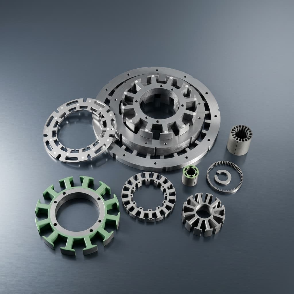
Direct Needle Winding on Segmented SMC Axial Flux Teeth: Slot Fill Factors, Wire Tension Fracture Limits, Corner Radius DFM, and Sourcing Controls
Compare direct needle winding on SMC axial flux teeth: copper fill, tension trials, corner radii and insulation. Prepare your drawing-led RFQ for DFM review.
Decision-level summary: Direct needle winding on segmented SMC axial flux teeth can improve access for concentrated coils, but achievable copper fill and acceptable wire tension depend on the complete tooth, insulation, fixture and winding program. A nominal tension setting or corner radius cannot establish a fracture limit. For sourcing, compare suppliers using the same gross-slot definition, instrumented winding trials and inspection of the wound corners. Release tooling only after mechanical integrity, dielectric performance and the assembled coil envelope have been demonstrated together.
Published and reviewed: November 10, 2026. Scope: Global B2B motor engineering, manufacturing and supplier quality for concentrated coils on individual soft magnetic composite (SMC) teeth. This guide covers round-wire winding and procurement controls for axial flux permanent magnet (AFPM) motors. Rectangular wire, Litz bundles, hairpins and completed safety-critical motor systems need separate qualification. The numerical examples below are reproducible calculations with stated assumptions, not measured production results or certified process limits.
Transitioning from magnetic simulation to automated coil winding? Request an engineering DFM review with your tooth CAD, wire specification, insulation concept and winding requirements. Our compaction tooling DFM guide covers tooling review, while manufacturing quality controls explain the evidence to agree before ordering.
1. Copper Fill Factors: Define the Denominator Before Comparing Suppliers
Segmenting a stator into individual teeth can provide external access for winding concentrated coils before assembly. Access still depends on pole-shoe overhangs, nozzle clearance and fixture placement. Segmentation alone does not guarantee orthocyclic packing, lower resistance or a particular motor efficiency. Compare complete winding layouts, including end turns, interconnections, insulation and cooling, rather than assigning a universal advantage over radial machines.
An orthocyclic winding places successive wire layers in the valleys of the preceding layer. The ideal infinite hexagonal packing fraction of identical circles is about 90.7%, but that is a local geometrical ceiling, not a realistic gross-slot copper target. Enamel, ground insulation, boundaries, crossovers and assembly clearances all consume space.
A_copper = N × π × d_bare² / 4
k_copper = A_copper / A_gross_slot
k_insulated = N × π × d_over_enamel² / (4 × A_gross_slot)
Use dimensions from the same cross-section. Here N counts conductor crossings in the selected coil side; do not count both sides of a coil against the area of only one slot. A supplier quoting packing inside the usable winding window must identify that smaller denominator separately from gross-slot fill.
Worked Fill-Factor Example: Copper Area Is Not Winding Feasibility
Assume a simplified 10 mm × 10 mm gross window, 30 conductor crossings, 1.60 mm bare copper diameter and 1.72 mm diameter over enamel. Bare copper area is 60.32 mm², giving 60.3% gross-slot copper fill. The insulated conductors occupy 69.71 mm², giving 69.7% insulated-wire fill. These percentages describe the same proposed winding and cannot be used interchangeably.
For an area-only comparison, reserve a uniform insulation thickness on all four sides. An assumed 0.20 mm layer leaves 92.16 mm²; an assumed 0.80 mm bobbin wall leaves 70.56 mm². These thicknesses are example inputs, not recommended insulation specifications. In the bobbin case, the proposed insulated conductors would occupy 98.8% of the remaining window, exceeding the ideal circular packing fraction. That proposal fails this simple packing screen. The thinner-layer case still needs finite-row layout and winding trials; passing an area calculation does not prove that 30 turns fit.
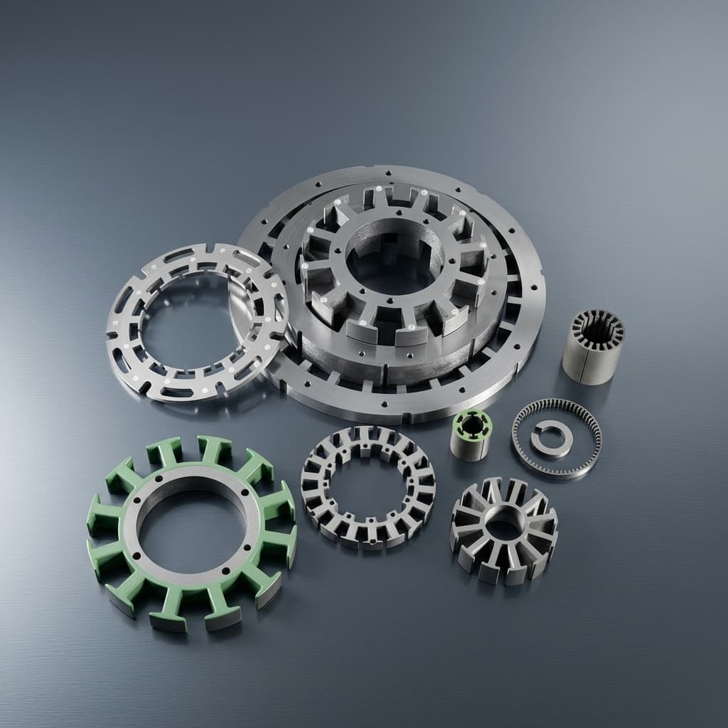
Figure 1: Core-shape illustration. This image does not show a validated single-tooth winding or establish a measured fill factor; use the calculation and winding layout for that decision.
What Segmented Winding Can Help You Control
- End-turn geometry: Compare conductor length from actual turn paths. Shorter end turns can reduce resistance, but terminal routing and coil separation may offset part of the gain.
- Layer placement: Agree the wire pitch, integer turn count and crossover location before accepting a fill-factor claim.
- Module testing: Test individual wound teeth before carrier assembly, then repeat the checks that assembly or potting could affect.
- Assembly clearance: Include the coil envelope and tooth positioning tolerance in rotor and adjacent-coil clearance calculations. A compact loose coil is not proof of an acceptable assembled stator.
2. Mechanical Fracture Risks Under Wire Tension
SMC consists of electrically insulated magnetic powder particles consolidated into a component. Material properties depend on the powder grade, compaction and heat treatment. For example, the manufacturer's Somaloy 3P product page identifies a particular processing route. Do not extend one product family's processing conditions or mechanical properties to every SMC tooth.
For winding, treat edges and thin shoes as potentially vulnerable to chipping and bending damage. Obtain grade-specific data and representative component tests. Transverse rupture strength (TRS) is a specimen bending result; it is not an allowable local compressive contact pressure, tensile strength or permitted clamping pressure. Comparing a calculated contact pressure directly with TRS cannot establish a safe winding load.
2.1 Measure Dynamic Tension at the Relevant Wire Path
A controller setpoint describes the tensioning system, not necessarily the peak tension at a tooth corner. Pay-off behavior, wire-guide friction, path changes, acceleration and layer transitions can change the load. Sensor position and sampling rate determine whether the recorded trace captures these events.
For an illustrative trial only, a 20 N setpoint and a recorded 36 N peak would mean a peak-to-setpoint ratio of 1.8. Neither value is an approved SMC limit. Record the sensor calibration, bandwidth, position, winding speed, wire size and tooth revision alongside the trace. Include startup, corners, crossovers and stopping; an average tension value can hide the event that damages a coating.
Use the following schematic to identify the contact path and fixture interface. Its simplified nesting pattern and support features do not prescribe a production tooth topology.
Figure 2: Winding contact-path schematic, not to scale. Corner geometry, coating continuity, tension and fixture support must be qualified together; no safe load or radius is implied.
2.2 A Force Calculation Does Not Establish a Fracture Limit
For an ideal frictionless guide that changes the wire direction through angle θ, equal tension T on both sides gives a resultant guide force of 2 × T × sin(θ / 2). At a 90-degree change and T = 36 N, that resultant is about 50.9 N. This is a force on the guide, not a contact pressure or SMC strength prediction. Real coated corners have friction, deformable insulation and a changing contact footprint.
A useful fracture assessment needs the local tooth geometry, coating behavior, loading direction, support conditions and material variability. Replace an unsupported Hertzian pressure shortcut with instrumented trials and, where necessary, a contact model calibrated against those trials. Examine both core damage and insulation damage: an intact-looking tooth can still have an abraded corner coating.
3. Corner Radius DFM and Tooling Feasibility Boundaries
Specify the winding-contact radius on the drawing, with its tolerance and inspection method. A general “break sharp edges” note does not define the final coated wire path. Distinguish the core radius, coating build at that radius and any bobbin lead-in feature. The wire touches the finished insulation surface, which may differ from the nominal CAD shape.
Larger radii can smooth the wire path, but they also alter magnetic cross-section and winding geometry. Whether a change increases or decreases usable copper space depends on which surface moves and which envelope stays fixed. Recalculate the actual section instead of assigning a universal fill-factor penalty. Tool life also depends on tooling material, press conditions, ejection and maintenance, so a radius alone cannot guarantee a number of press cycles.
Corner and Wire-Path Release Matrix
| Control point | Drawing or process input | Evidence needed before release |
|---|---|---|
| Core contact radius | Radius, tolerance and location at every wire contact | Measured first-article profile against the drawing |
| Finished insulation radius | Coating build or molded lead-in geometry | Section or validated surface measurement at the corner |
| Wire bend compatibility | Bare diameter, enamel build and supplier bending requirements | Wound-corner inspection with the specified wire |
| Pole-shoe transition | Minimum ligament, overhang and nozzle clearance | Tooling review and demonstrated collision-free path |
| Compaction and ejection | Press direction, density risk and support during handling | Supplier DFM disposition and trial-part inspection |
| Dynamic winding load | Speed, acceleration, tension trace and layer transitions | Trial record tied to the exact tooth and fixture revision |
| Final coil envelope | End-turn, adjacent-coil and rotor-clearance limits | Gauge or dimensional report after winding and assembly |
If the wire path is still uncertain, submit the tooth section and insulation concept for DFM review before freezing tooling. Ask the supplier to identify which drawing features are feasible as pressed and which need additional processing and inspection.
4. Insulation Comparison: Direct Powder Coating vs. Molded Bobbins
Direct-on-core winding means winding over a deliberately specified insulation system on the core. Interparticle electrical insulation within SMC does not itself qualify the external surface as winding-to-core insulation. Choose that barrier for the complete electrical, thermal, chemical and mechanical duty.
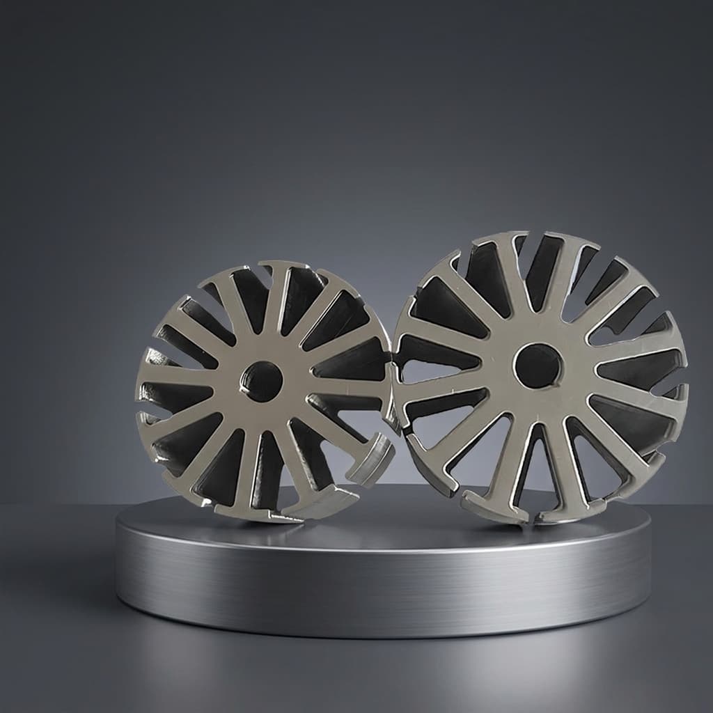
Figure 3: Illustrative core geometry without installed copper coils. It does not show a completed wound module, cooling circuit or insulation qualification.
4.1 Injection-Molded Bobbins
A bobbin can provide a controlled wire path, terminal routing and a barrier between wire and core. It may spread local contact load, but that load still reaches the core through the bobbin and fixture. It cannot guarantee zero edge damage. Minimum wall thickness, mold flow, seams and fit need review for the selected resin and geometry.
Reserve the actual wall, flange and assembly-clearance dimensions in the winding layout. Evaluate heat transfer through the complete interface, including gaps and impregnation, rather than predicting continuous torque from a generic plastic conductivity. A resin temperature rating alone does not establish the thermal endurance of the assembled insulation system.
4.2 Direct-on-Core Epoxy Powder Coating
A qualified coating can use less winding-window space than a particular bobbin design, but its local thickness, adhesion, cure and corner coverage become process controls. Review the coating application and cure with the SMC supplier. Inspect edges, recesses and fixture-contact areas rather than relying only on a flat-surface thickness measurement.
The 800V SiC slot insulation guide explains why DC bus voltage and a Hipot result cannot establish repetitive-pulse qualification. A thinner barrier is useful only if it survives winding, assembly and the intended operating environment.
Insulation Sourcing Comparison
| Decision factor | Molded bobbin | Direct coating | Buyer acceptance evidence |
|---|---|---|---|
| Window reservation | Walls, flanges and fitting clearance | Local coating thickness and clearance | Layout using the same gross-slot denominator |
| Wire contact | Molded surface, seams and lead-ins | Coated core corners and transitions | Inspection after representative winding |
| Mechanical load path | Bobbin transfers load to core and fixture | Load passes through coating into core | Qualified tension and fixture setup |
| Thermal behavior | Resin, gaps and impregnation affect resistance | Coating and contact quality affect resistance | Temperature assessment on the intended assembly |
| Dielectric behavior | Wall integrity and interface geometry | Pinholes, edge coverage and abrasion | Agreed system-level qualification and routine tests |
| Process traceability | Resin lot, molding settings and fit | Powder lot, preparation and cure record | Revision-controlled manufacturing records |
| Cost and delivery | Mold, parts, assembly and inspection | Masking, coating, cure and inspection | Quote tied to volume, yield and acceptance scope |
| Environmental durability | Resin and joint compatibility | Coating adhesion and chemical compatibility | Agreed aging conditions followed by electrical checks |
5. Winding Kinematics: Needle, Rotating Spindle and Slip-On Coils
Choose a winding method around physical access and the complete cycle, not a generic fill-factor ranking. Machine axis count and terminology vary; ask for a demonstrated wire path on the proposed tooth. A flyer rotates the wire delivery mechanism, while a spindle arrangement rotates the workpiece. Neither name alone establishes tension stability.
5.1 CNC Needle Winding
The tooth remains stationary while the nozzle follows a programmed path and indexes turns. This can help with asymmetric modules and terminal routing. Check nozzle clearance throughout the cycle, including the final layers. Evaluate path acceleration and tension control at corners, not just nominal machine speed.
5.2 Rotating-Tooth Spindle Winding
The fixture rotates the tooth while the wire guide controls placement. This can suit accessible, suitably balanced modules, but workpiece rotation creates its own wire-path and retention demands. Confirm fixture balance, tooth support and loose-lead management. Continuous spindle rotation does not guarantee constant tension around a noncircular section.
5.3 Pre-Formed Slip-On Coils
A separate mandrel carries winding loads before the coil is installed on the insulated tooth. This removes winding contact from the core, but insertion, bonding and final retention still create loads. Shoe overhangs may prevent installation unless the core or assembly sequence permits it. Check the inserted coil for insulation damage and movement after assembly.
| Selection question | Needle winding | Rotating spindle | Pre-formed slip-on coil |
|---|---|---|---|
| What moves? | Wire-delivery nozzle | Tooth and fixture | Separate mandrel during winding |
| Main access check | Nozzle path around shoes and leads | Rotating envelope and guide clearance | Coil insertion past shoes |
| Core loading | Wire contact and static fixture | Wire contact plus rotating fixture | Insertion and assembly loads |
| Layer placement | Programmed path and pitch | Guide pitch and spindle synchronization | Mandrel geometry and transfer stability |
| Main trial record | Tension versus path position | Tension versus rotation and speed | Coil dimensions before and after insertion |
| Cycle-time comparison | Include loading and lead routing | Include loading, retention and stopping | Include bonding, transfer and insertion |
| Quote boundary | Fixture, programming and inspection | Fixture, guarding and inspection | Mandrel, bonding and assembly tooling |
6. Winding Arbor and Clamping DFM for SMC Cores
Fixture damage can occur before the first turn is wound. Support the actual tooth topology: a yokeless segment may have no back-iron face, so a universal back-iron datum instruction would be inappropriate. Avoid loading unsupported shoes or thin edges, and locate the part using agreed robust surfaces.
A conformal nest or suitable compliant pad can distribute load, but pad thickness, hardness, wear and chemical compatibility must be qualified. Excessive compliance can let the tooth move and abrade its coating. Record total actuator force and actual contact area. Dividing force by nominal pad area gives only average pressure; it does not reveal edge peaks or bending stress.
Separate clamping qualification from wire-tension qualification. Inspect clamped but unwound parts, then wind representative parts using the same fixture revision. Use a suitable contact-pressure mapping method where helpful, with an appropriate measurement range. Define fixture cleaning, pad replacement, force checks and how operators detect mis-seating. There is no universal 12 MPa or 15 MPa acceptance limit established by this guide.
7. Wire Specification and Inverter-Fed Dielectric Stress
Specify bare conductor diameter, diameter over enamel, tolerances, insulation build, chemistry, thermal class and the exact wire specification. The publisher's IEC 60317-0-1 record identifies general requirements for enamelled round copper wire. Use the relevant product-specific specification and agreed edition as well; a general wire standard does not qualify a wound motor module.
Select the enamel build with the actual bend, abrasion and electrical requirements. Do not assume that one build grade is always adequate or inadequate for every SMC geometry. Likewise, do not equate a wire's thermal class with the endurance of a system containing coating, bobbin, impregnant and lead insulation.
For converter-fed operation, define the voltage waveform at the winding, including repetitive peak voltage, rise time, cable arrangement, temperature and relevant environmental conditions. An 800V DC bus does not determine a single PDIV requirement. Keep sinusoidal PDIV and repetitive-pulse measurements distinct and identify the waveform used in each report.
IEC 60034-18-41 addresses qualification and quality-control testing of Type I converter-fed machine insulation systems. Its public catalogue record supports that scope, not a universal 1.4 multiplier, fixed test voltage or guaranteed lifetime. The responsible electrical engineer must select the applicable insulation-system approach and tests. Agree routine withstand, surge and resistance checks separately from design qualification; a Hipot pass does not replace pulse-voltage evaluation.
8. Supplier Quality Acceptance Checklist
Use this checklist to turn a quote into an agreed control plan. Set numerical limits from the released design and qualification evidence, with named responsibility for core, insulation, winding and assembly interfaces.
- 1. Drawing revision: Identify every wire-contact radius, fragile feature, datum and finished coil envelope. Resolve conflicting title-block edge notes.
- 2. Material identity: Record the exact SMC grade, processing route, lot traceability and agreed material tests. State whether data comes from coupons or actual teeth.
- 3. Insulation coverage: Define local thickness, cure, adhesion and defect criteria, including corners and fixture-contact areas. Validate the chosen measurement method.
- 4. Bobbin fit, if used: Check wall and flange dimensions, seams, lead routing and assembly loads against the released layout.
- 5. Tension envelope: Approve a calibrated dynamic trace covering the full winding cycle. Tie limits to wire, tooth, insulation and machine settings.
- 6. Fixture controls: Approve the support surfaces, force settings, pad condition, seating checks and clamped-part inspection.
- 7. Electrical tests: Agree qualification and routine tests with voltage, waveform, duration, temperature, instrumentation and acceptance criteria. Identify which checks apply to every module.
- 8. Resistance measurement: Use a suitable calibrated method and temperature correction; agree module and assembled-phase limits from the winding design.
- 9. Corner inspection: Include unwound controls and sacrificial wound samples. Distinguish damage caused during winding from damage caused while removing wire for inspection.
- 10. Assembly and change control: Check the final envelope and repeat relevant electrical checks after assembly. Require review when material, coating, wire, tooling or winding settings change.
For a qualification trial, include representative material lots and dimensional extremes, then record the sampling rationale, observed defects and unresolved conditions. Zero failures in a small sample does not establish zero production risk. Retain traceability from each wound sample to its tension trace and inspection report. The manufacturing quality page provides context for agreeing documentation and inspection scope.
9. Frequently Asked Questions
Can segmented SMC teeth be wound without a bobbin or powder coating?
Do not treat the powder's interparticle insulation as a qualified external dielectric barrier. A separate validated insulation arrangement is needed for the intended wire-to-core duty. Coating and bobbins are common options, but other engineered barriers may be suitable. The decision requires electrical and mechanical evidence for the finished module, rather than an assumed surface resistance.
What is the maximum practical copper fill factor for direct needle winding?
There is no universal maximum for SMC teeth. The worked example gives 60.3% bare-copper fill from stated conductor and gross-window dimensions; it is a calculation, not an achieved winding result. Ask for turn count, section dimensions, enamel diameter, insulation reservation and measured coil envelope before comparing supplier percentages.
What wire tension or corner radius prevents SMC fracture?
Neither variable can be approved independently. Material condition, tooth geometry, wire bend, coating, fixture support and dynamic loading all matter. Establish a process envelope through representative trials and inspection, with suitable engineering margins. A TRS value cannot be converted directly into a safe corner contact pressure.
How does winding tension affect PDIV?
Contact and movement during winding can damage enamel or ground insulation, changing electrical performance. The amount depends on the insulation system and loading history. Compare representative wound samples under the agreed waveform and conditions; this guide does not establish a numerical PDIV reduction or a universal tension threshold.
Should we buy bare teeth or complete wound modules?
Choose based on interface ownership, in-house capability and the supplier's demonstrated scope. Bare teeth require the buyer to control insulation and winding interfaces. Wound modules can simplify accountability if acceptance tests and change control are explicit. Compare total accepted-module cost, including tooling, scrap, inspection and assembly, rather than imposing a universal order-volume threshold. Confirm offered delivery scope in the quotation.
10. Sources and Evidence Boundaries
- IEC — IEC 60317-0-1:2013, general requirements for enamelled round copper winding wire. Official base-publication record, with related amendments identified by the publisher. Supports wire-specification scope; agree the applicable edition and product-specific requirements.
- IEC — IEC 60034-18-41:2014, Type I converter-fed rotating-machine insulation systems. Official base-publication record with amendment information. Supports insulation-system qualification scope, not the numerical acceptance limits of an individual module.
- Höganäs — Somaloy 3P. Manufacturer product information illustrating why material and processing requirements must be grade-specific. Does not provide a universal winding-tension limit or corner-radius rule.
Evidence boundary: Public source identity and scope checked November 10, 2026. Catalogue descriptions are not a review of every normative clause in a purchased standard. The fill-factor, window-area and wire-deflection examples are editorial calculations, not first-party manufacturing trials. No production scrap-rate, tooling-life, PDIV or motor-performance guarantee is claimed. Obtain current supplier data and application-specific qualification records before design release.
11. Engineering Review and Sourcing Next Steps
Prepare an RFQ that lets the core supplier, insulation processor and winder quote the same deliverable:
- Tooth CAD and drawing revision, contact radii, datums and assembly envelope.
- Wire specification, conductor and enamel dimensions, turn count and gross-slot fill definition.
- Proposed insulation system, winding method and available trial data.
- Operating waveform, thermal and environmental requirements, and electrical qualification plan.
- Required delivery state, volume, inspection scope, traceability and change-approval responsibilities.
Send your tooth CAD and winding requirements for a DFM and quotation review. Ask the review to identify unresolved geometry, process and test boundaries before committing production tooling. Delivery scope and acceptance evidence should be confirmed in the project quotation.
Use the compaction tooling DFM guide for press and ejection questions, and the modular stator tooth retention guide for the next assembly interface after winding.
Article-to-RFQ Workflow
Turn this guide into an evidence-ready RFQ.
Use the article context as the starting point, then align CAD status, magnetic targets, validation scope, and release records before asking suppliers to quote.
Capture the decision
Identify the topology, product family, operating point, and current gate before the article takeaway becomes a supplier question.
Attach buyer inputs
Prepare drawing status, magnetic targets, quantity plan, destination, and open risks in the RFQ worksheet.
Request evidence
Ask for DFM notes, first article inspection, magnetic validation, traceability, and packaging release files before price comparison.
Author

Categories
More Posts
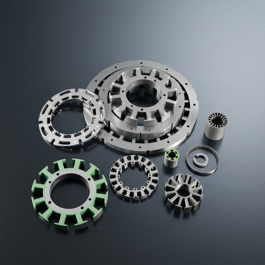
Axial Flux Motor Topologies (YASA, AFIR, TORUS): A Core Sourcing & Procurement Guide
Compare YASA, AFIR, and TORUS axial flux motor topologies for stator core sourcing, SMC vs laminated steel choices, RFQ risk control, and DFM review.
Thermal Management in Axial Flux Motors: Direct Oil Cooling and Stator Core Design
Engineering guide to axial flux motor thermal management, direct oil cooling, SMC stator design, validation risks, supplier evidence, and RFQ checks for buyers.
SMC vs. Laminated Steel for Axial Flux Motor Cores: A Procurement & Engineering Guide
An in-depth guide for procurement teams and engineers evaluating Soft Magnetic Composites (SMC) against laminated steel for axial flux motor cores.